11.Connect external cables to the installed card, if needed. Connect internal cables to the system board, if needed.
12.Reconfigure the computer, if necessary.
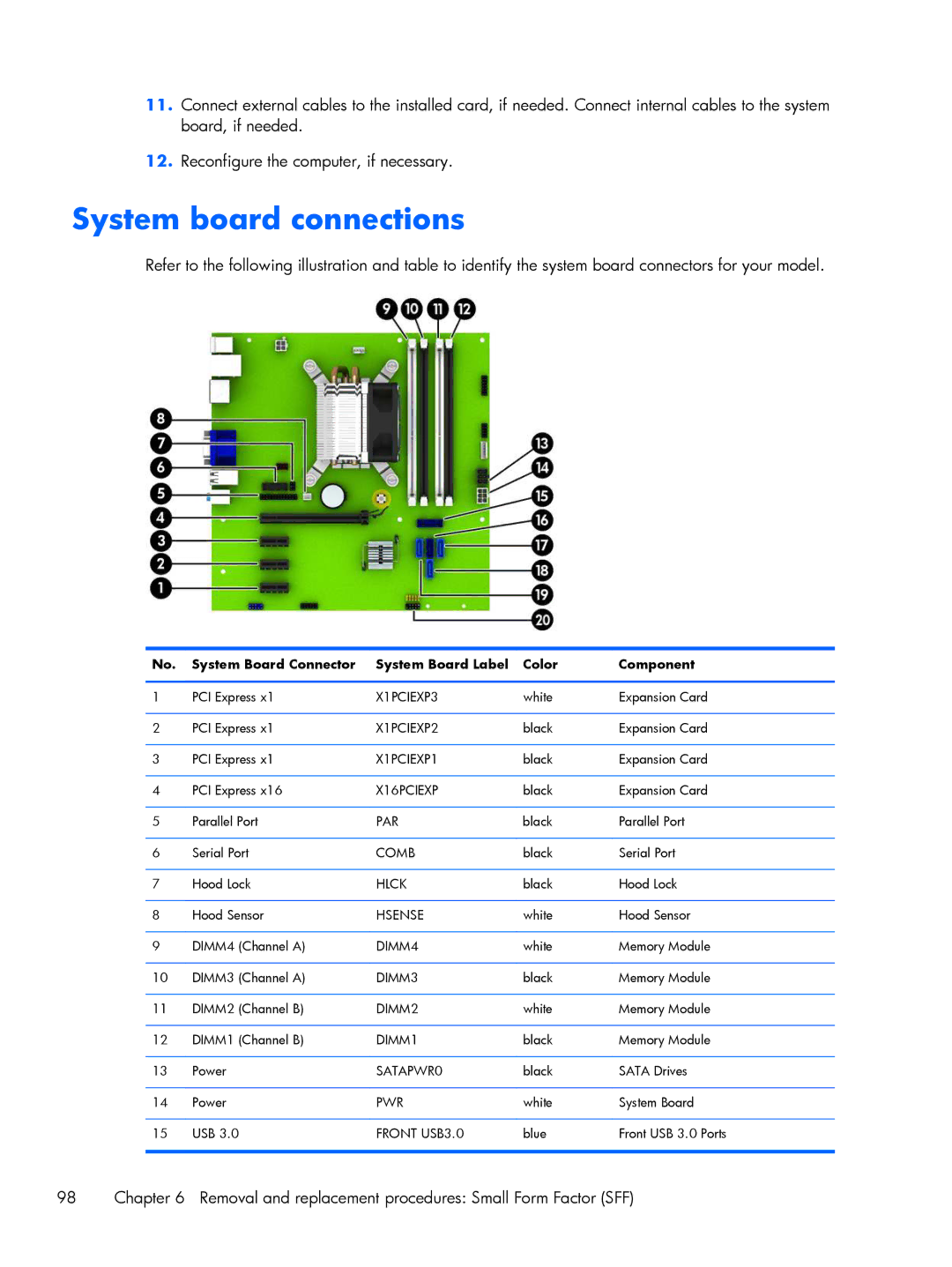
System board connections
Refer to the following illustration and table to identify the system board connectors for your model.
No. | System Board Connector | System Board Label | Color | Component |
|
|
|
|
|
1 | PCI Express x1 | X1PCIEXP3 | white | Expansion Card |
|
|
|
|
|
2 | PCI Express x1 | X1PCIEXP2 | black | Expansion Card |
|
|
|
|
|
3 | PCI Express x1 | X1PCIEXP1 | black | Expansion Card |
|
|
|
|
|
4 | PCI Express x16 | X16PCIEXP | black | Expansion Card |
|
|
|
|
|
5 | Parallel Port | PAR | black | Parallel Port |
|
|
|
|
|
6 | Serial Port | COMB | black | Serial Port |
|
|
|
|
|
7 | Hood Lock | HLCK | black | Hood Lock |
|
|
|
|
|
8 | Hood Sensor | HSENSE | white | Hood Sensor |
|
|
|
|
|
9 | DIMM4 (Channel A) | DIMM4 | white | Memory Module |
|
|
|
|
|
10 | DIMM3 (Channel A) | DIMM3 | black | Memory Module |
|
|
|
|
|
11 | DIMM2 (Channel B) | DIMM2 | white | Memory Module |
|
|
|
|
|
12 | DIMM1 (Channel B) | DIMM1 | black | Memory Module |
|
|
|
|
|
13 | Power | SATAPWR0 | black | SATA Drives |
|
|
|
|
|
14 | Power | PWR | white | System Board |
|
|
|
|
|
15 | USB 3.0 | FRONT USB3.0 | blue | Front USB 3.0 Ports |
|
|
|
|
|
98 | Chapter 6 Removal and replacement procedures: Small Form Factor (SFF) |