CEC 1 | CEC 2 |
CPU 1 ![]()
![]() CPU 2
CPU 2 ![]()
![]() CPU 3
CPU 3 ![]()
![]() CPU 4
CPU 4
400 MHz | 3.2 GBps | |
|
|
|
32 MB |
| Processor & |
L4 cache | 3.2 GBps | cache controller |
|
|
|
SMP Expansion Ports (3.2GBps)
CPU 4 |
| CPU 3 |
| CPU 2 |
| CPU 1 |
| ||||
|
|
|
|
|
|
|
|
|
|
|
|
| 3.2 GBps |
| 400 MHz | ||||||||
|
|
|
|
|
|
|
|
|
|
|
|
Processor & |
|
|
| 32 MB | |||||||
cache controller | 3.2 GBps | L4 cache | |||||||||
|
|
|
|
|
|
|
|
|
|
|
|
|
|
|
|
|
|
|
|
|
|
| 3.2 GBps |
|
|
| SDRAM |
|
|
|
|
|
| 3.2 GBps |
|
| |
|
|
|
|
|
|
|
|
| Memory | |||
|
|
|
|
|
|
|
|
|
|
| ||
|
| SDRAM |
|
|
|
|
|
| controller | |||
|
|
|
|
|
| 3.2 |
| |||||
|
|
|
|
|
|
|
|
|
|
|
| |
|
|
|
|
|
|
|
|
| GBps |
|
|
|
|
|
|
|
|
|
|
|
|
|
|
| |
|
| SDRAM |
|
|
|
|
|
| 2 GBps | |||
|
|
|
|
|
|
|
| |||||
|
|
|
|
|
|
| ||||||
|
|
|
|
|
|
|
|
|
|
| ||
|
| SDRAM |
|
|
|
| 100 MHz | |||||
|
|
|
|
| ||||||||
|
|
|
|
|
|
|
|
|
|
|
|
|
RXE
Expansion
Port B
(1 GBps)
3.2 GBps
Memory controller
2 GBps
3.2GBps
3.2 GBps
100 MHz
![]() SDRAM
SDRAM ![]()
![]()
![]() SDRAM
SDRAM ![]()
![]() SDRAM
SDRAM ![]()
![]()
![]() SDRAM
SDRAM ![]()
RXE Expansion |
| PCI bridge | 66 MHz |
Port A (1 GBps) |
|
| |
|
|
| |
|
|
|
|
Bus A
PCI bridge
66 MHz
Ultra160
SCSI
Gigabit
Ethernet
33MHz
![]() Video
Video
![]() USB
USB
![]() Kbd/Ms
Kbd/Ms
![]() RSA
RSA
|
IBM
66 MHz | 100 MHz | 133 MHz |
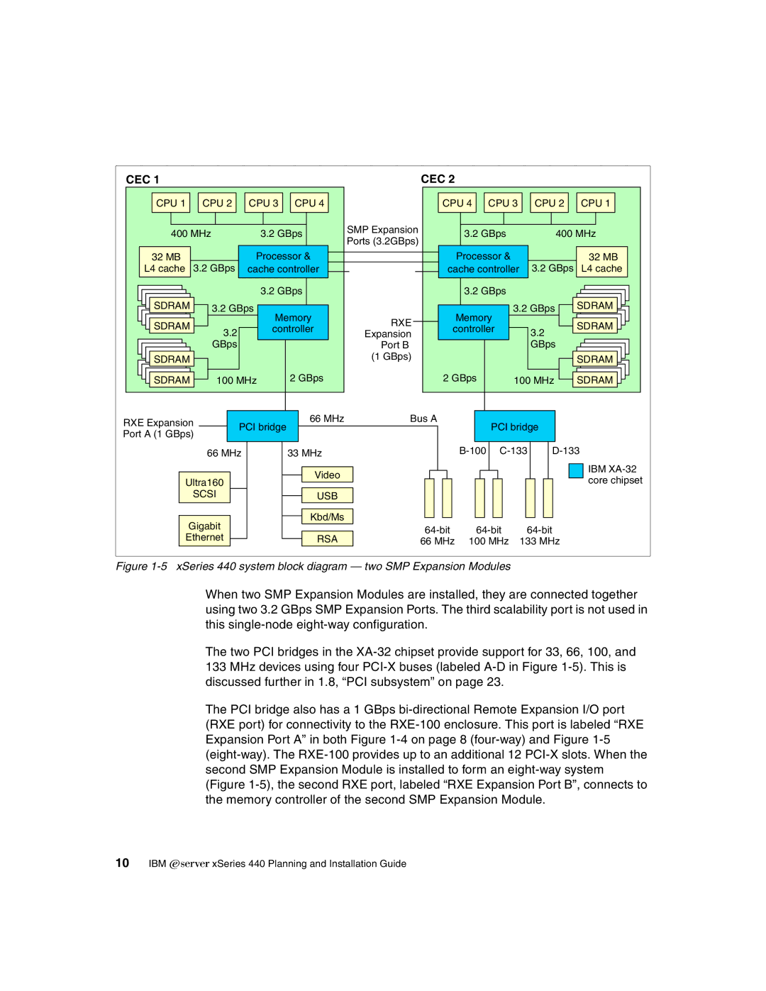
Figure 1-5 xSeries 440 system block diagram — two SMP Expansion Modules
When two SMP Expansion Modules are installed, they are connected together using two 3.2 GBps SMP Expansion Ports. The third scalability port is not used in this
The two PCI bridges in the
133MHz devices using four
The PCI bridge also has a 1 GBps