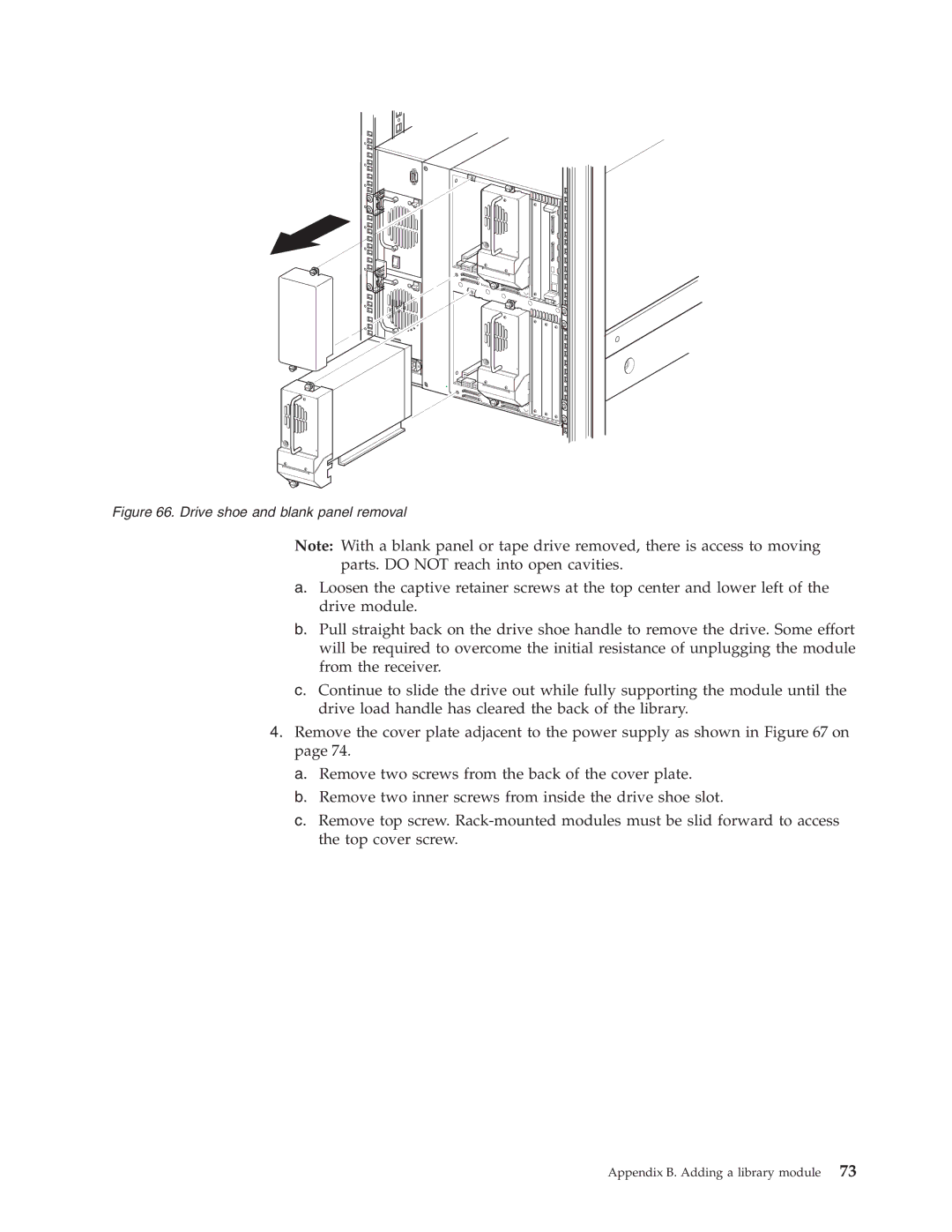
Figure 66. Drive shoe and blank panel removal
Note: With a blank panel or tape drive removed, there is access to moving parts. DO NOT reach into open cavities.
a.Loosen the captive retainer screws at the top center and lower left of the drive module.
b.Pull straight back on the drive shoe handle to remove the drive. Some effort will be required to overcome the initial resistance of unplugging the module from the receiver.
c.Continue to slide the drive out while fully supporting the module until the drive load handle has cleared the back of the library.
4.Remove the cover plate adjacent to the power supply as shown in Figure 67 on page 74.
a.Remove two screws from the back of the cover plate.
b.Remove two inner screws from inside the drive shoe slot.
c.Remove top screw.
Appendix B. Adding a library module 73