Intermate100 / Intermate101
Trademarks
Disclaimer
Introduction
Target Audience and Products
Introduction
Target Audience
Print Servers, Component Codes and Release Levels
August 2001 IPP October 2001 ThinPrint
Summary overview of major changes Spring
December
January 2002 IPX/SPX removed
Introduction Target Audience and Products
Types of Documentation
Print Server Administration Manual
Manual and Guides
Other Types of Documentation
Conventions Used in the Manual and Guides
Purpose of the About informa- tion
Topics in This Manual
About the Supported Printing Environments
About the FTP Print protocol
About Tools for Management and Configuration
Descriptive Framework
About Initial Contact
Powerful Multi Purpose Utility
Getting
Connected
Basic sub-group has three configuration pages
About Configuring the Basic and Permission Sub- Groups
Key Concepts
About Configuring Services and Host-Sessions
Input control and HPOs
Target printer
Logical printer
Configuration Pages for Output and Input
Processing Facilities
Output Control
Input Control Sub-Group
Input Five Sub-Groups
Other Configurations
About Information and Monitoring Possibilities
Chapters on upgrades and maintenance
About Upgrades and Maintenance
Maintenance-related items on the Http menu
About the Appendices
Printing Environments
Windows 2000 and Windows XP
What is a printer
Introduction
Raw Socket Printing Standard TCP/IP Port
Page
Page
Native LPR
LPR
Intermate Print Port
Print queue nameip address
Windows 2000 and Windows XP LPR
Http//192.168.0.227631/printer
Internet Print Protocol
Windows 2000 and Windows XP Internet Print Protocol
Windows NT
Install the Print Port Program
Using an Intermate Print Port for Raw Socket or
Define Printer and Port
Page
Setting up a Raw Socket Port Port
Print queue nameip address
Page
Prerequisite
Native LPR
Windows NT 4.0 Native LPR
\systemroot\SYSTEM32\DRIVERS\ETC
Windows NT 4.0 Native LPR
Add the Intermate Port 9100 or LPR printer port
Windows 95/98
Install the Print Port Program
New Printer
Windows 95/98 New Printer
Add the Intermate Port 9100 or LPR printer port
Setting up a Raw Socket Port Port
Print queue nameip address
Page
Novell Netware LPR via pure IP
Apple LaserWriter LPR only
Mac OS 8.1 and higher
To set up for printing
Viewer.html?docid=0900253d80006cfa&docheader=ter- minal
Mac OS 7.5 or Earlier
Topics Covered
AIX
Initialization Screen
LPR Ascii
Field Comments
FTP
How to Print LPD
Create a new Ipds printer definition
Ipds with PSF/6000
Checking and Using the Ipds Connection
General Printing Problems for AIX
Ipds
OS/2 2.x and OS/2 Warp
Create a new printer and queue
LPR Ascii data, e.g. PCL and Postscript
Para
Print from WIN-OS/2 using the Lprmon command
Print using LPR command from the Command Line
Element Replace with
To obtain status from the TCP/IP LPD connected printer
Troubleshooting
System requirements
Ipds from PSF/2
OS/2 2.x and OS/2 Warp Ipds from PSF/2
Tools for Management Configuration
Prerequisites
Http Browser
Http//192.168.0.227
How To Connect
Actions
Menu Items and Groups Before Login
Tip
Login with User Name and Password
Menu Items and Groups After Login
At the bottom of each configuration page are three buttons
How to Change Settings on Configuration Pages
Activating New Values By Rebooting
Log out from the Intermate1xx by closing the browser window
Logout
Connecting
Configuration Using a Telnet Client
Setting Up Telnet Terminal Preferences
Platform Prerequisites
Configuration Menus
Menu Items and Settings
Main Menu
Commands below, interface means Intermate1xx print server
What the Imcuimcu is and how It works
Intermate Management and Configuration Utility Imcu
This Chapter Covers Installation and Basic Use
Installation of the Various Elements
Establishing an Imcu Server
Log
How to Log In and Out
Sample device list is shown on the next
Device List / Available Agents
Device List
Remote Installation of an Agent from the Imcu server
Installing Agents
Troubleshooting Agent Installation on a PC
Direct Installation of an Agent on a PC
Embedded Agent on the Intermate1xx
Initial Contact
IP Assignments for Initial Contact
Host Name
Information Needed Before Starting
How to find the group of settings called TCP/IP
Ipconfig Windows NT 4.0, Windows 2000 or XP
Method Overview
IP Assignments for Initial Contact Method Overview
Etc/bootptab file
Assignment Using Bootp
IP Assignments for Initial Contact Assignment Using Bootp
192.168.0.227 00c0a200801e
Assignment Using Rarp
IP Assignments for Initial Contact Assignment Using Rarp
Assignment Using Dhcp
Arp -s 192.168.0.227 00-c0-a2-00-80-1e
Static IP Assignment Using ARP and Ping
Page
Prerequisites
Static IP Assignment Using the Imcu
Steps
Page
Configuring Basic Permissions SUB-GROUPS
TCP/IP
Enable DHCP, BOOTP, RARP-or none of these
Syntax for IP Address, Subnet Mask, and Default Gateway
Mandatory IP-identifying information
Host Name
DNS Server for Look-Ups
Optional Settings
Wins Server
Introduction to the Chapter
General
SysAdmin contact
Administrative Parameters
Model
Device’s location
System Target Printer has the following special functions
System Target Printer
Values Comments
Enable Front Panel Messages PJL
Media speed and duplex
Network
Enable Local MAC Address
7F.FF.FF.FF.FF.FF
Local MAC Address
Password Change
Configuring Permissions
Enter New Password
Re-enter Password
Ordering a key
License Key
About the Global MAC Address
License Key Entry
Configuring Print Services and Host Sessions
Processing Facilities
Services
TCP/IP Sessions, Services and Host-Sessions
HPO SCS TN5250E Host Sessions
HPO SCS TN3270E Host Session
HPO Ipds Host Session
Physical Printers = Target Printers
Network Printers Using NDO
Local Printer
System Target Printer
Processing layers. Read from left to right
Processing Layers
Old Use Logical
Use Logical Printer/Output To
Printer
Logical Printers
Configurable Logical Printers
17.6.1. PR0 / Logical Printer
Physical printer
How Strings Are Written
String Substitution
Examples of Logical Printer Definitions
Data Manipulation in the Logical Printer Layer
Substitution
Logical Pre-Processing String Before
Printer Strings
PR0
Processing Flows-Examples
SCS TN3270 through PR0 Logical Printer
PR5 configured for string before and string after
Load Balancing Pools NDO only
Logical
Working with NDO Load Balancing Pools and Data Manipulation
Pre-Processing Post-Processing
Printer Pool Strings
LPR-4
Types Logical Load Pre-Processing Post-Processing
Local Printer Parallel Port
Supports 1284 Directional Be enabled?
Introduction-Messages and Status Reporting
Is the result bi
See About Error Reporting in ECP Mode
Values for print servers using releases 2111 and higher
Parallel Port Ieee P1284 Negotiation Mode
Values for print servers using releases older than
Value Comments
Value
Ieee Timing Log for ECP and Nibble Modes
PJL Support
Report Compatible Mode PE as
Compatible Mode, Report Problems As
Report Compatible Mode Error as
Check for Pending Printer Data When Idle For / Reverse Data
Special PJL Settings for ECP and Nibble
PJL Printer Status Feedback Frequency
Value for Comments
ECP Mode on a printer that understands PJL
About Error Reporting in ECP Mode
ECP Mode on a printer that does not understand PJL
Disable this if you are using NDO
Enable Power Detection
Network Destination Option
Recommended Features for Network Target Printers
Requirements
Brushed-up Functionality and Terminology
Configurations for Each Network Destination #
Hostname Mandatory
LPR
Print Method Mandatory
Raw Socket port numbers
Raw Socket TCP Port
Printer LPR Queue Name
LPR settings
LPR Count Byte MB
Local Printer-Do Not Enable Power Detection
Changes Needed on Other Configuration Pages
System Target Printer in a Stand-Alone Setup
Target Printer 1-2 mandatory fields
Logical Printers
Up to 3 optional fields for data manipulation
Order of fields within each set
Target Printer
Determining the order of values to enter
Load Balancing Pool
Example Comments 3,2
500 100 200
String Before and String After
String Substitutions
Input String # and Output String#
Substitution Strings
Planning
Common Feature How to Direct Output
Services in Input Control
Advanced Settings
More informa- tion
Raw Socket = Port 9100 = Reverse Telnet
Example TCP Port # 1 set to
Special Ispp port
Example TCP Port # 4 set to
Name
LPR Print Queues LPD Protocol
Queue Name Queue Type Output is directed to
Using FTP Print
Configuration
FTP Print
Print server configuration
Included Features
Printer configuration and use
IPP Print Internet Printing Protocol
ThinPrint
ThinPrint configuration page in the Intermate1xx
Introduction
Services in Input Control ThinPrint
Intermate1xx
Value Where the output is sent by the print server
Management Information Monitoring Possibilities
Main Status Pages
Other Printouts in the Actions Group
Help Quick Guide
Status Group on the Http Menu
Standard Monitoring Information
Target Name Local Printer
Status Target Printer Info
Target Name Network Destination
About Network Target Printers
About the Page Counters
Effect of Local Printer Negotiation Modes
Target Name Local Target
Status System Log
Messages about things you can fix yourself
Messages requiring you to seek help from a point of purchase
Imcu Agent
Configurable Monitoring Tools
Mail Notification
Parameter Default Comments Setting
Introduction and Pre-Requisites
Configure Snmp
To set up a connection
Set Up a Connection With Your Snmp Tool
Configure Snmp Set Up a Connection With Your Snmp Tool
Configure Snmp Set Up a Connection With Your Snmp Tool
To define a query and edit variables
Edit Variables
To add the Private MIB
Load and Edit Options Parameters
To edit the Intermate1xx parameters
Tip
Traps
To set up traps
Parameter
6.1.4.1.1527
00000000400c0a20507f8
Reboot the Intermate1xx
Look up the number in . Snmp Printer Trap Numbers
Using and Viewing Traps
Configure Snmp Using and Viewing Traps
Purposes and Limitations
Printer and Job Status via Finger External Tool
Finger @192.168.0.227
How to Use It
Upgrades and Maintenance
How to Get Upgrades
Upgrade Components
How to See Which Firmware is Currently Loaded
What and How
Two Part Version-Naming System
What the Firmware File Names Mean
Release Level Designations
Overview of Component Types and File Names
File Name
FSS-Files
Configuration file imacfg.bin
Configuration Files
28.4.2. .IDB
Intermate100 G22
Print Server’s FTP Directory and Its Libraries
Intermate101 G32 and G34
Dir
How to Inspect the FTP Directory
Upgrades of Firmware and Fonts FFS files
Using FTP Directly
Put C\PrintServerUpdates\G222021.FFS
Upgrades of IDBs
Imacfg.bin
Binary Configuration File imaconfig.bin
Put C\PrintServerConfigs\imacfg.bin
Advantages
Using the Imcu for Maintenance
Single Print Server
About file types
FFS files, such as Main Code
Configuration file
Using the Imcu for Maintenance Single Print Server
Bulk Upgrade
Using the Imcu for Maintenance Bulk Upgrade
Cable
Upgrade of Main Code or Boot Code Using a Serial Cable
Intermate Download Utility Program
Activate New, Saved Settings with a Reboot
Overview of Types of Resets
Http Menu Configuration Page Only
Restore Factory Default Settings Remote
Http Menu Restore All Defaults
Telnet Client
Intermate100
Restore Factory Defaults Test Button
General Information
Result
Desired Result LED lighting sequence
Crash Recovery Intermate101 only
Appendices
Appendix A. Customer Support
Updates and Revised Documentation Where to Find Support
Gathering Information
Hardware
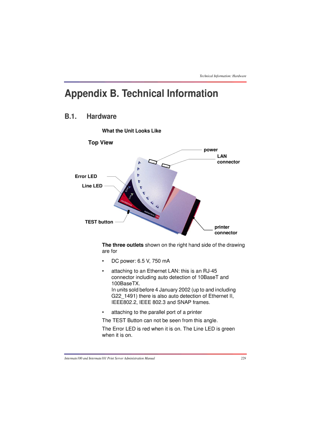
Appendix B. Technical Information
What the Unit Looks Like
Technical Information Hardware
Intermate100
Supported Printers and Performance Features
USA FCC Rules Part 15, Class a
Emission Notices and Approvals
EU EMC, CE Declaration of Conformity
Appendix C. Hardware Installation
LED Patterns in Various Modes
Programming Flash Memory
Test Button to Print Main Status Pages or Quick Guide
Hex
Appendix E. US Ascii 7-bit Character Set Decimal Values 32
112 113 114 115 116 117 118 119 120 121 122 123 124 125 126
Basic Rules and Encoded Bytes
Appendix F. String Syntax
Valid Strings
Examples of Valid Strings and Invalid Strings
Invalid Strings Why
Overall Checklist
Appendix G. Configuration Checklists
FTP
Printer Definitions on the Host
Checklist for Each Service or Host Session
Page
Cannot print a job
Appendix H. Troubleshooting
Cannot Ping the printer
Introduction
Printing Environments
Tools for Management and Configuration
Initial Contact
106
103
110
113
Configuring Print Services and Host-Sessions
151
144
157
170
159
173
180
178
194
197
206
Appendices