Getting Started Guide
Software License
Iii
End User License Agreement
Page
Abbreviated Table of Contents
Page
Table of Contents
Viii Table of Contents
Chapter PIM and VoIP Module Overview
Part Installing a Services Router
103
117
131
Part Maintaining Services Router Hardware
153
161
171
213
Xii Table of Contents
209
247
Part Series Requirements and Specifications
223
Xiv Table of Contents
Part
About This Guide
Objectives
Audience
Objectives
How to Use This Guide
Xvi How to Use This Guide
Location of J-series Information
Series Tasks Location of Instruction
Document Conventions
Text and Syntax Conventions
Related Juniper Networks Documentation
Web GUI Conventions
Related Juniper Networks Documentation
Series Guides and Related Junos Software Publications
Getting Started Guide for Your Router
Xx Related Juniper Networks Documentation
Series Services Router Administration Guide
Chapter in a J-series Guide
Documentation Feedback
Documentation Feedback
Requesting Technical Support
Self-Help Online Tools and Resources
Xxii Requesting Technical Support
Series Overview
Series Overview
Page
J2320 Services Router Overview
Overview of Services Routers
J2320 Services Router Overview
J2350 Services Router Overview
J2350 Services Router Overview
J4350 Services Router Overview
J4350 Services Router Overview
Overview of Services Routers
J6350 Services Router Overview
J6350 Services Router Overview
Series Software Features and Licenses
Summary of J-series Features and License Requirements
Feature Category Series Feature Separate License
Series Software Features and Licenses
Routing
Multicast
IP Address
Management
Encapsulation Ethernet
Security
Voice Support
High Availability
Traffic Analysis
Administration
Monitoring
Page
J2320 and J2350 Services Router Hardware Features
J2320 and J2350 Services Router Hardware Features
System Overview
J2320 and J2350 Chassis
14 J2320 and J2350 Services Router Hardware Features
Front of J2320 Chassis
Front of J2350 Chassis
Rear of J2320 Chassis
Rear of J2350 DC-Powered Chassis
J2320 Hardware Components
J2320 and J2350 Physical Specifications
Description Value
J2320 and J2350 Routing Engine Hardware
18 J2320 and J2350 Services Router Hardware Features
J2320 and J2350 Midplane
J2320 and J2350 Boot Devices
J2320 and J2350 Front Panel
Physical Interface Modules PIMs
Power Button and Power LED
20 J2320 and J2350 Services Router Hardware Features
Color State Description
J2320 and J2350 Power LED
J2320 and J2350 Status LED
22 J2320 and J2350 Services Router Hardware Features
Reset Config Button
J2320 and J2350 Alarm LED
Built-In Gigabit Ethernet Ports
Console Port
AUX Port
Gigabit Ethernet Port LEDs
J2320 Power System
J2350 Power System
24 J2320 and J2350 Services Router Hardware Features
J2320 and J2350 External Compact Flashes
J2320 and J2350 Cooling System
J4350 and J6350 Services Router Hardware Features
26 J4350 and J6350 Services Router Hardware Features
J4350 and J6350 Services Router Hardware Features
J4350 and J6350 Chassis
Rear of J4350 AC-Powered Chassis
Front of J4350 and J6350 Chassis
Rear of J4350 DC-Powered Chassis
J4350 and J6350 Physical Specifications
30 J4350 and J6350 Services Router Hardware Features
J4350 and J6350 Routing Engine Hardware
J4350 and J6350 Boot Devices
J4350 and J6350 Midplane
32 J4350 and J6350 Services Router Hardware Features
J4350 and J6350 Front Panel
Slot Number Diagram on Front Panel
Power LED
Status LED
Alarm LED
34 J4350 and J6350 Services Router Hardware Features
Reset Config Button
J4350 Power System
36 J4350 and J6350 Services Router Hardware Features
State Description
J6350 Power System
Power Supply LED
38 J4350 and J6350 Services Router Hardware Features
J4350 and J6350 Cooling System
Software Overview
Software Overview
Junos Software Processes
Routing Engine and Packet Forwarding Engine
Kernel and Microkernel
Process Name Description
User Interfaces
Junos Software Processes
Software Overview
PIM and VoIP Module Terms
PIM and VoIP Module Overview
PIM and VoIP Module Terms
PIM and VoIP Module Terms
Term Definition
PIM and VoIP Module Overview
Dialer filter
Field-Replaceable PIMs
Field-Replaceable PIMs
J2320 and J2350 Field-Replaceable PIM Summary
J4350 and J6350 Field-Replaceable PIM Summary
J2320 and J2350 Field-Replaceable PIM Summary
J4350 and J6350 Field-Replaceable PIM and Module Summary
Port, 6-Port, 8-Port, and 16-Port Gigabit Ethernet uPIMs
Fe-3/0/0
16-Port Gigabit Ethernet uPIM
TX/RX
Parameter 1000Base-SX Transceiver 1000Base-LX Transceiver
Port Gigabit Ethernet ePIMs
Optical Interface Support for SFP Gigabit Ethernet uPIMs
SFP Gigabit Ethernet ePIM
Optical Interface Support for SFP Gigabit Ethernet ePIM
Color State Description
Dual-Port Serial PIM
Status LEDs for Serial Ports
Dual-Port T1 or E1 PIM
Dual-Port T1 PIM
Dual-Port Channelized T1/E1/ISDN PRI PIM
Status LEDs for T1 and E1 Ports
LEDs for Channelized T1/E1/ISDN PRI PIMs
Label Color State Description
T3 or E3 PIM
T3 PIM
Dual-Port Fast Ethernet PIM
Status LEDs for T3 and E3 Ports
Port Fast Ethernet ePIM
LEDs for Dual-Port Fast Ethernet PIM
Port Isdn BRI PIMs
LEDs for 4-Port Fast Ethernet ePIM
Isdn BRI U PIM
LEDs for Isdn BRI S/T and U PIMs
Adsl PIM
LEDs for Adsl PIMs
Shdsl PIM
Avaya VoIP Modules
Avaya VoIP Modules
LEDs for G.SHDSL PIMs
Avaya VoIP Module Summary
J2320 and J2350 Avaya VoIP Module Summary
J4350 and J6350 Avaya VoIP Module Summary
TIM521 BRI
TGM550 Telephony Gateway Module
TGM550 Telephony Gateway Module
Additional Information
Hardware or Feature TGM550 Maximum Capacity
TGM550 Maximum Media Gateway Capacities
LEDs for TGM550 Gateway Module
ASB
TIM508 Analog Telephony Interface Module
TIM508 Possible Port Configurations
Possible Analog Telephone Line Configurations
TIM510 E1/T1 Telephony Interface Module
LEDs for TIM508
TIM514 Analog Telephony Interface Module
LEDs for TIM510
LEDs for TIM514
TIM514 Possible Port Configurations
TIM516 Analog Telephony Interface Module
LEDs for TIM516
TIM516 Possible Port Configurations
Possible Analog Telephone Line Line Configurations
TIM518 Possible Port Configurations
TIM518 Analog Telephony Interface Module
TIM521 BRI Telephony Interface Module
LEDs for TIM518
LEDs for TIM521
Services Router User Interface Overview
User Interface Overview
Web Overview
User Interface Overview
Before You Begin
CLI Overview
Before You Begin
Using the J-Web Interface
Services Router User Interface Overview
Using the J-Web Interface
Starting the J-Web Interface
Elements of the J-Web Interface
Web Layout
Top Pane Elements
Main Pane Elements
Side Pane Elements
Main Pane Elements
Navigating the J-Web Interface
Side Pane Elements
Navigating the Quick Configuration Pages
Navigating the J-Web Configuration Editor
Web Quick Configuration Buttons
Key J-Web Edit Configuration Buttons
Getting J-Web Help
Web Sessions
CoS Help
Using the Command-Line Interface
Using the Command-Line Interface
CLI Command Hierarchy
CLI Operational Mode
Starting the CLI
CLI Configuration Mode
CLI Basics
Editing Keystrokes
Task Category Action Keyboard Sequence
Command Completion
CLI Editing Keystrokes
Online Help
Configuring the CLI Environment
Help Commands
Configuring the CLI Environment
Set cli screen-width
Set cli terminal
Ansi
Vt100
Page
Installing a Services Router
Installing a Services Router
Page
General Site Guidelines
Preparing for Router Installation
General Site Guidelines
Rack Requirements
Rack Requirements
Rack Size and Strength for J2320 and J2350 Routers
Connection to Building Structure
Preparing for Router Installation
Rack Size and Strength for J4350 and J6350 Routers
Fire Safety Requirements
Router Environmental Tolerances
Fire Suppression
Router Environmental Tolerances
Fire Suppression Equipment
Power Guidelines, Requirements, and Specifications
Power Guidelines, Requirements, and Specifications
Site Electrical Wiring Guidelines
Signaling Limitations
Radio Frequency Interference
Electromagnetic Compatibility
Specification
Router Power Requirements
AC Power, Connection, and Power Cord Specifications
AC Power Cord Specifications
Country Electrical Specifications Plug Standards
DC Power, Connection, and Power Cable Specifications
Planning for Power Management
Name Model Number
Series PIM Power Consumption and Heat Dissipation
Tokens Junos CLI Low Power High Power
Maximum Power and Heat Capacities of J-series Models
Model Low- Power Capacity High- Power Capacity Tokens
Network Cable Specifications
Site Preparation Checklist
Site Preparation Checklist
Isdn Provisioning
Page
Installing and Connecting a Services Router
Unpacking a J-series Services Router
Unpacking a J-series Services Router
Installing J2320 and J2350 Routers
Installing J2320 and J2350 Routers
Installing and Connecting a Services Router
Installing J4350 and J6350 Routers
Installing J4350 and J6350 Routers
Installing the Mounting Brackets
Attaching Center Screw to the Rack
Chassis Grounding
Connecting Interface Cables to Services Routers
Connecting Interface Cables to Services Routers
Connecting Power
Connecting Power
Connecting AC Power
Connecting AC Power to the J2320 Services Router
Connecting DC Power
Connecting AC Power to the J2350 Services Router
VDC and RTN
Connecting DC Power to the J2350 Services Router
Powering a Services Router On and Off
Powering a Services Router On and Off
Page
Establishing Basic Connectivity
Basic Connectivity Terms
Basic Connectivity Terms
Term Definition
Basic Connectivity Overview
Basic Connectivity Overview
Router Identification
Root Password
Network Settings
Time Zone and System Time
Establishing Basic Connectivity
Default Gateway
Backup Router
Loopback Address
Built-In Ethernet Interface Address
Management Access
Configuration Guide for Common Criteria and JUNOS-FIPS
Connecting to a Services Router
Connecting to a Services Router
Connecting to the J-Web Interface
Connecting to a Services Router
Connecting to the CLI Locally
COM1
Connecting to the Console Port on J2320 and J2350 Routers
Connecting to the CLI Remotely
Configuring the Modem at the Router End
Connecting the Modem to the Console Port
Configuring Basic Settings with J-Web Quick Configuration
Configuring Basic Settings with J-Web Quick Configuration
Connecting to the CLI at the User End
Set Up Quick Configuration
Set Up Quick Configuration Summary
Field Function Your Action
Identification
Time
Set Up Quick Configuration Summary
Field Function
Network
Ge-0/0/0 Address
Configuring Basic Settings with a Configuration Editor
Sample Settings on a Services Router
Configuring Basic Settings
Task Web Configuration Editor CLI Configuration Editor
Set backup router address
Set ntp server
Set name-server
Displaying Basic Connectivity Configurations
Verifying Basic Connectivity
Displaying Basic Connectivity Configurations
151
Page
Configuring Secure Web Access
Secure Web Access Terms
Secure Web Access Terms
Secure Web Access Terms
Secure Web Access Overview
Secure Web Access Overview
Generating SSL Certificates
Configuring Secure Web Access
Configuring Secure Web Access
Quick Configuration Secure Access
Secure Access Quick Configuration Summary
Http Web Access
Https Web Access
Certificates
Configuring Secure Web Access with a Configuration Editor
Secure Access Quick Configuration Summary
Configuring a Secure Web Access
Configuring Secure Web Access with a Configuration Editor
Verifying Secure Web Access
Displaying an SSL Certificate Configuration
Displaying a Secure Access Configuration
Displaying a Secure Access Configuration
Installing and Managing J-series Licenses
Series License Overview
License Enforcement
Series License Overview
Software Feature Licenses
Series Services Router Software Feature Licenses
Licensed Software Feature License Name
License Key Components
Feature Summary
Installed Licenses
Managing J-series Licenses with the J-Web Interface
Summary of License Management Fields
Adding New Licenses with the J-Web Interface
Deleting Licenses with the J-Web Interface
Displaying License Keys with the J-Web Interface
Downloading Licenses with the J-Web Interface
Managing J-series Licenses with the CLI
Adding New Licenses with the CLI
Deleting a License with the CLI
Managing J-series Licenses with the CLI
Displaying Installed Licenses
Saving License Keys with the CLI
Verifying J-series License Management
Verifying J-series License Management
Displaying License Usage
Displaying Installed License Keys
Displaying License Usage
Displaying Installed License Keys
Maintaining Services Router Hardware
Maintaining Services Router Hardware
Page
Tools and Parts Required
Replacing Hardware Components
Tools and Parts Required
Replacing the Console Port Cable
Replacing a PIM
Removing a PIM
Tools and Parts Required
Replacing Hardware Components
Replacing a PIM
Installing a PIM
Installing a PIM
Installing PIM Cables
Replacing PIM Cables
Removing PIM Cables
Replacing PIM Cables
User@host request chassis fpc slot pim-slotonline
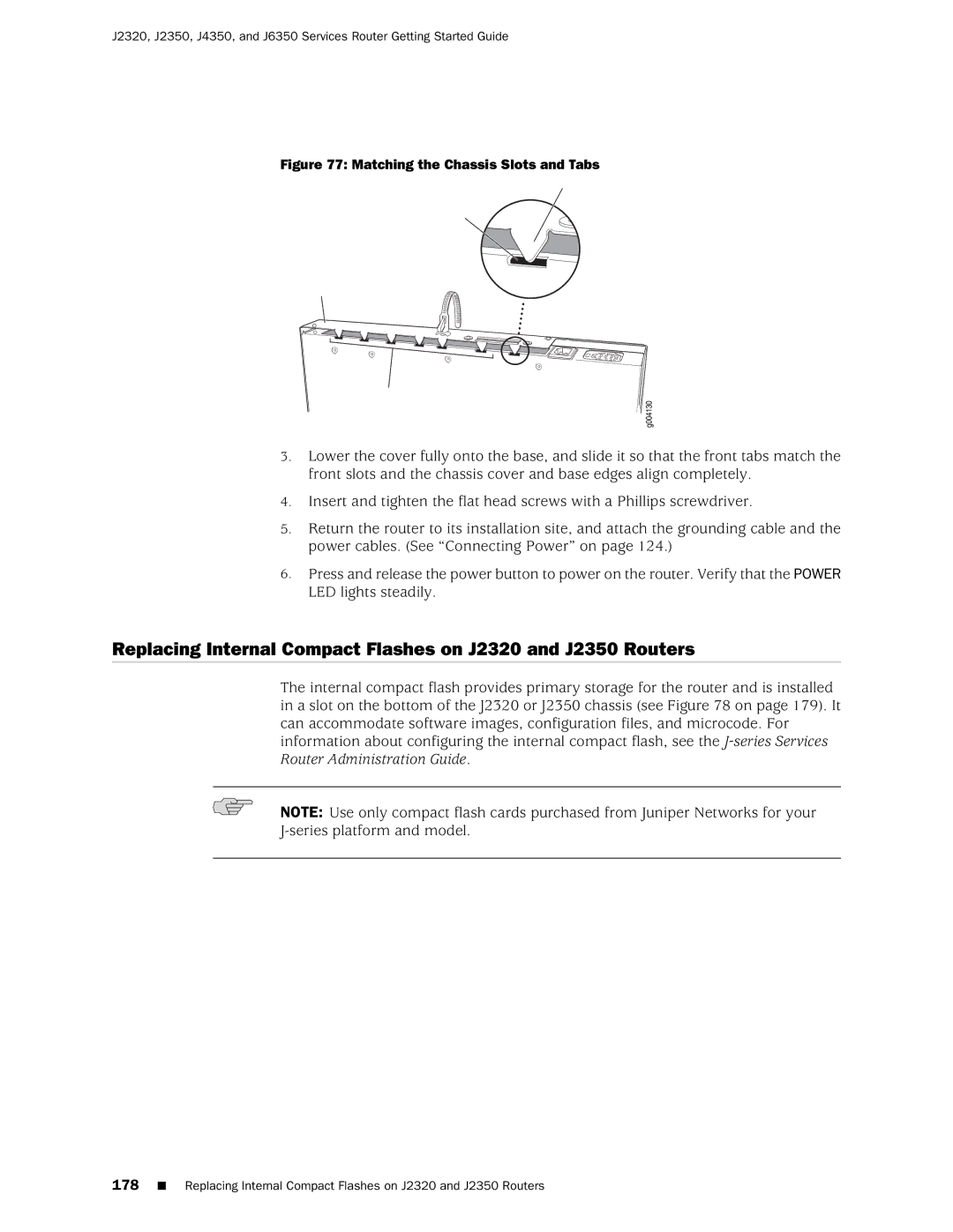
To replace the cover on the J2320 and J2350 chassis
Matching the Chassis Slots and Tabs
Location of J2320 and J2350 Internal Compact Flash
Removing the J2320 or J2350 Internal Compact Flash
Location of J4350 and J6350 Compact Flash
Page
Removing the J4350 or J6350 Compact Flash
Replacing External Compact Flashes
Replacing External Compact Flashes
Replace the compact flash slot cover
Replacing USB Storage Devices
Replacing USB Storage Devices
Removing the USB Storage Device
Installing the USB Storage Device
Replacing Dram Modules
Replacing Dram Modules
Removing a Dram Module
J4350 and J6350 Dram Location
Installing a Dram Module
Installing or Replacing Dram Modules
Replacing Power System Components
Replacing Power System Components
Replacing AC Power Supply Cords
Removing an AC Power Supply from J6350 Routers
Installing an AC Power Supply in J6350 Routers
Removing an AC Power Supply
Replacing DC Power Supply Cables
Installing an AC Power Supply
Removing a DC Power Supply
Installing a DC Power Supply
Removing a DC Power Supply
VDC and RTN
Installing a DC Power Supply
Removing a J2320 or J2350 Crypto Accelerator Module
Removing a J2320 or J2350 Crypto Module
Installing a J2320 or J2350 Crypto Accelerator Module
Installing a J2320 or J2350 Crypto Accelerator Module
User@host show chassis hardware
Removing a J4350 or J6350 Crypto Accelerator Module
Removing a J4350 or J6350 Crypto Module Screw
Installing a J4350 or j6350 Crypto Accelerator Module
Replacing Air Filters on J2350 Routers
Replacing Air Filters on J2350 Routers
Replacing Air Filters on J4350 and J6350 Routers
Replacing Air Filters on J4350 and J6350 Routers
Attaching Air Filter and Filter Cover
Page
Troubleshooting Hardware Components
Chassis Alarm Conditions
Chassis Alarm Conditions and Corrective Actions
Component Alarm Conditions Corrective Action Alarm Severity
Troubleshooting Power Management
Troubleshooting Power Management
Troubleshooting Hardware Components
User@host show chassis fpc
Contacting the Juniper Networks Technical Assistance Center
Contacting the Juniper Networks Technical Assistance Center
Locating Component Serial Numbers
Contacting Customer Support and Returning Hardware
Locating Component Serial Numbers
J2320 and J2350 Chassis Serial Number and Agency Labels
Location of the Serial Number ID Labels
J4350 and J6350 Chassis Serial Number and Agency Labels
Contacting Customer Support and Returning Hardware
Power Supply Serial Number Labels
Return Procedure
PIM Serial Number Label
Contacting Customer Support
Packing a Router or Component for Shipment
Packing a Router or Component for Shipment
Tools and Parts Required
Packing the Services Router for Shipment
Packing Components for Shipment
Contacting Customer Support and Returning Hardware
Page
Series Requirements and Specifications
Series Requirements and Specifications
Page
Network Cable Specifications and Connector Pinouts
Serial PIM Cable Specifications
Port Serial PIM Cables and Connectors
Serial PIM Cable Specifications
RS-232 DTE Cable Pinout
LFH-60 Pin DB-25 Pin LFH-60 Pairing Description
RS-232 DTE Cable Pinout
RS-232 DCE Cable Pinout
RS-422/449 EIA-449 DTE Cable Pinout
RS-232 DCE Cable Pinout
RS-422/449 EIA-449 DTE Cable Pinout
Receive Data a
RS-422/449 EIA-449 DCE Cable Pinout
RS-422/449 EIA-449 DCE Cable Pinout
EIA-530A DTE Cable Pinout
EIA-530A DTE Cable Pinout
EIA-530A DCE Cable Pinout
EIA-530A DCE Cable Pinout
35 DTE Cable Pinout
LFH-60 Pin 34 Pin LFH-60 Pairing Description
DTE Cable Pinout
LFH-60 Pin DB-15 Pin LFH-60 Pairing Description
DCE Cable Pinout
35 DCE Cable Pinout
21 DTE Cable Pinout
21 DCE Cable Pinout
Fast Ethernet RJ-45 Connector Pinout
Gigabit Ethernet uPIM RJ-45 Connector Pinout
Fast Ethernet RJ-45 Connector Pinout
Gigabit Ethernet uPIM RJ-45 Connector Pinout
Gigabit Ethernet ePIM RJ-45 Connector Pinout
Gigabit Ethernet ePIM RJ-45 Connector Pinouts
Pin Signal Name
Gigabit Ethernet ePIM RJ-45 Connector Pinout
E1 and T1 RJ-48 Cable Pinouts
RJ-45 Chassis Console Connector Pinout
DB-9 Console Connector Pinout
236 E1 and T1 RJ-48 Cable Pinouts
RJ-48 Connector to RJ-48 Connector Straight Pinout
RJ-48 Connector to RJ-48 Connector Crossover Pinout
RJ-48 Connector to DB-15 Connector Straight Pinout
RJ-48 Connector to DB-15 Connector Crossover Pinout
E3 and T3 BNC Connector Pinout
Adsl and G.SHDSL RJ-11 Connector Pinout
Adsl and G.SHDSL RJ-11 Connector Pinout
PinSignal
Isdn RJ-45 Connector Pinout
Connector Pinouts for Avaya VoIP Modules
Isdn RJ-45 Connector Pinout
Isdn RJ-45 Connector Pinout
TGM550 RJ-11 Connector Pinout for Analog Ports
TGM550 RJ-45 Console Connector Pinouts
TGM550 RJ-11 Connector Pinout
TGM550 RJ-45 Pin Signal Terminal DB-9 Pins
TIM508 Connector Pinout
TIM510 RJ-45 Connector Pinout
TIM508 Connector Pinout
TIM510 RJ-45 Connector Pinout
TIM514 Connector Pinout
TIM516 Connector Pinout
TIM514 RJ-11 Connector Pinout
TIM516 Connector Pinout
TIM516 Connector Pinout
TIM518 Connector Pinout
TIM518 Connector Pinout
TIM521 Connector Pinout
TIM521 RJ-45 Connector Pinout
Page
Definition of Safety Warning Levels
Safety and Regulatory Compliance Information
Definition of Safety Warning Levels
Definition of Safety Warning Levels
Safety Guidelines and Warnings
General Safety Guidelines and Warnings
Safety and Regulatory Compliance Information
Safety Guidelines and Warnings
Qualified Personnel Warning
Preventing Electrostatic Discharge Damage
Place a Component into an Electrostatic Bag
Electrical Safety Guidelines and Warnings
General Electrical Safety Guidelines
AC Power Electrical Safety Guidelines
DC Power Electrical Safety Guidelines
Power Sources for Redundant Power Supplies
DC Power Disconnection Warning
Safety Guidelines and Warnings
DC Power Grounding Requirements and Warning
DC Power Wiring Sequence Warning
Varten 48 V, +RTN varten +RTN, maajohto maajohtoon
DC Power Wiring Terminations Warning
Grounded Equipment Warning
Case of Electrical Accident
Multiple Power Supplies Disconnection Warning
Power Disconnection Warning
TN Power Warning
Telecommunication Line Cord Warning
Chassis Lifting Guidelines
Installation Safety Guidelines and Warnings
Installation Instructions Warning
Rack-Mounting Requirements and Warnings
Safety Guidelines and Warnings
Safety and Regulatory Compliance Information
Safety Guidelines and Warnings
Laser and LED Safety Guidelines and Warnings
Ramp Warning
General Laser Safety Guidelines
Class 1 Laser Product Warning
Class 1 LED Product Warning
Laser Beam Warning
Radiation from Open Port Apertures Warning
Maintenance and Operational Safety Guidelines and Warnings
Battery Handling Warning
Jewelry Removal Warning
Lightning Activity Warning
Operating Temperature Warning
Safety Guidelines and Warnings
Product Disposal Warning
Agency Approvals
Agency Approvals
Lithium Battery
Compliance Statements for Environmental Requirements
Compliance Statements for Nebs
Compliance Statements for EMC Requirements
Canada
Compliance Statements for EMC Requirements
European Community
Japan
FCC Part 68 Statement
United States
FCC Part 15 Statement
Compliance Statements for EMC Requirements
Index
Index
Page
Symbols
Alternative boot media See boot devices USB
Reset Config
See also LEDs
Daemons See processes, software
Eprom
Gigabit Ethernet ports
Installation
Hardware Installation 119
E3 PIM
Link
Internal compact flash 178
Adsl
Power LED
Rescue configuration, resetting with Rescue Config
265
SSH
System overview Hardware Software System time
See also Junos CLI
EMI