Rear Rack Bracket Mounting Instructions
To install a Tiernan unit in a standard
1.Attach the mounting plates to both sides of the unit:
a.The mounting plates have a series of oblong slots and two small holes which are
b.Line up the small holes on the mounting plate with the mounting holes located on the unit towards the rear of each side panel.
c.Thread a mounting screw through the bracket and into the Tiernan unit. The screw should be flush with the plate when tightened.
ANALOG |
|
|
|
|
|
|
| SERIAL DIGITAL |
|
|
|
|
VIDEO IN VIDEO OUT | GENLOCK |
|
|
|
|
| VIDEO IN | VIDEO OUT | GENLOCK |
|
| 0 |
|
| J4 |
| J5 |
| J6 | J7 |
|
| J19 | J20 | |
|
| RIGHT | LEFT |
| RIGHT | LEFT |
|
| 4A |
| 4B | Fuse |
J2 | J3 | A |
|
|
|
| J16 | J17 | J18 | SERIAL DIGITAL AUDIO |
| |
|
|
|
|
|
| J8 | J9 |
|
|
|
|
|
|
|
|
| TX IF OUT |
| MOD ASI IN |
|
| ASI OUT |
|
| |
|
| J11 | J12 | J13 | J14 | J15 |
|
|
|
|
|
|
|
|
|
|
| DTE |
|
|
|
|
|
|
|
ETHERNET FAULT DCE | J21 | J22 | J23 | J24 | ||
CONTROL | RELAY | CONTROL | ||||
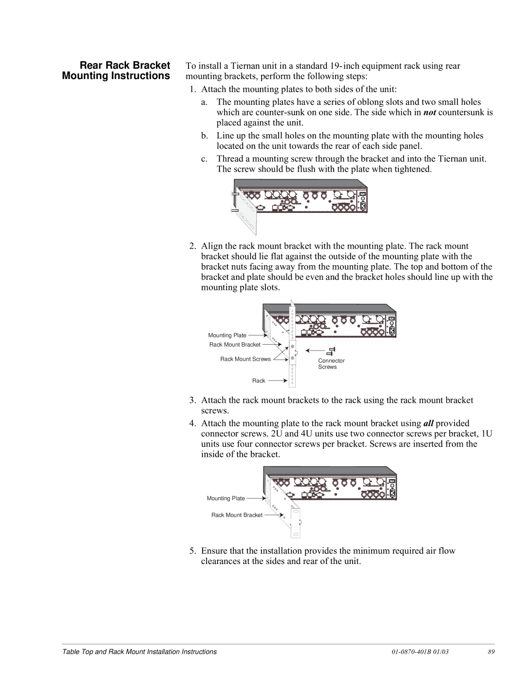
2.Align the rack mount bracket with the mounting plate. The rack mount bracket should lie flat against the outside of the mounting plate with the bracket nuts facing away from the mounting plate. The top and bottom of the bracket and plate should be even and the bracket holes should line up with the mounting plate slots.
ANALOG |
|
|
|
|
|
|
| SERIAL DIGITAL |
|
|
|
|
VIDEO IN VIDEO OUT GENLOCK |
|
|
|
|
| VIDEO IN | VIDEO OUT | GENLOCK |
|
| 0 | |
|
|
| J4 | J5 |
| J6 | J7 |
|
| J19 | J20 | |
|
| RIGHT | LEFT |
| RIGHT | LEFT |
|
| 4A |
| 4B | Fuse |
J2 | J3 | A |
|
|
|
| J16 | J17 | J18 | SERIAL DIGITAL AUDIO |
| |
|
|
|
|
|
| J8 | J9 |
|
|
|
|
|
|
|
|
| TX IF OUT |
| MOD ASI IN |
|
| ASI OUT |
|
| |
|
|
| J12 |
|
| MUX ASI IN | PRIMARY SECONDARY |
|
| |||
| J1 |
| J13 | J14 | J15 |
|
|
|
|
|
| |
|
|
|
|
| DTE |
|
|
|
|
|
|
|
Mounting Plate |
|
| ETHERNET FAULT DCE |
|
| J21 | J22J23 | J24 |
| |||
|
| CONTROL | RELAY |
| CONTROL |
|
|
| ||||
|
|
|
|
|
|
|
|
|
|
|
| |
Rack Mount Bracket |
|
|
|
|
|
|
|
|
|
|
|
|
Rack Mount Screws |
|
|
|
|
| Connector |
|
|
|
| ||
|
|
|
|
|
| Screws |
|
|
|
|
| |
Rack |
|
|
|
|
|
|
|
|
|
|
|
|
3.Attach the rack mount brackets to the rack using the rack mount bracket screws.
4.Attach the mounting plate to the rack mount bracket using all provided connector screws. 2U and 4U units use two connector screws per bracket, 1U units use four connector screws per bracket. Screws are inserted from the inside of the bracket.
| ANALOG |
|
|
|
|
|
|
| SERIAL DIGITAL |
|
|
|
|
|
VIDEO IN | VIDEO OUT | GENLOCK |
|
|
|
|
| VIDEO IN | VIDEO OUT | GENLOCK |
|
|
| 0 |
|
|
|
| J4 | J5 |
| J6 | J7 |
|
| J19 |
| J20 | |
|
|
| RIGHT | LEFT |
| RIGHT | LEFT |
|
| 4A |
|
| 4B | Fuse |
| J2 | J3 | A |
|
|
|
| J16 | J17 | J18 | SERIAL DIGITAL AUDIO |
| ||
|
|
|
|
|
|
| J8 | J9 |
|
|
|
|
|
|
|
|
|
|
| TX IF OUT |
| MOD ASI IN |
|
| ASI OUT |
|
| ||
|
|
|
| J12 |
|
| MUX ASI IN | PRIMARY | SECONDARY |
|
| |||
|
| J11 |
| J13 | J14 | J15 |
|
|
|
|
|
|
| |
|
|
|
|
|
| DTE |
|
|
|
|
|
|
|
|
Mounting Plate |
|
|
| ETHERNET FAULT DCE |
|
| J21 | J22 | J23 | J24 |
| |||
|
|
| CONTROL | RELAY |
| CONTROL |
|
|
| |||||
|
|
|
|
|
|
|
|
|
|
|
|
|
| |
Rack Mount Bracket ![]()
![]()
5.Ensure that the installation provides the minimum required air flow clearances at the sides and rear of the unit.
Table Top and Rack Mount Installation Instructions |
| 89 |