North American Applications
One cord has an
International Applications
The international cord has an
Connecting to a Power Source
To connect to an AC power source, follow these steps:
1.Select an AC power cord. If an international power cord is selected, attach a connector in accordance with local regulations and laws.
2.Ensure the TDR6 power switch is in the Off, or 0, position.
3.Connect the female plug of the AC power cord to the AC power receptacle on the TDR6 rear panel.
4.Connect the male plug of the AC power cord to an external AC power conditioning surge suppressor.
5.Connect the AC power conditioning surge suppressor to an AC outlet.
CAUTION!
Please Read
Carefully
Corrupted AC input power can interrupt TDR6 operations and cause permanent damage to the unit. You should purchase and install a commercially available, external AC power conditioning surge suppressor to protect the TDR6 against power spikes and line transients.
Power-up Sequence
Once the cabling and interconnections for the TDR6 are completed, you may
The power switch is labelled with a — and an 0. The — represents the On position, while the 0 represents the Off position.
To power up the TDR6, press the power switch to the ON, or
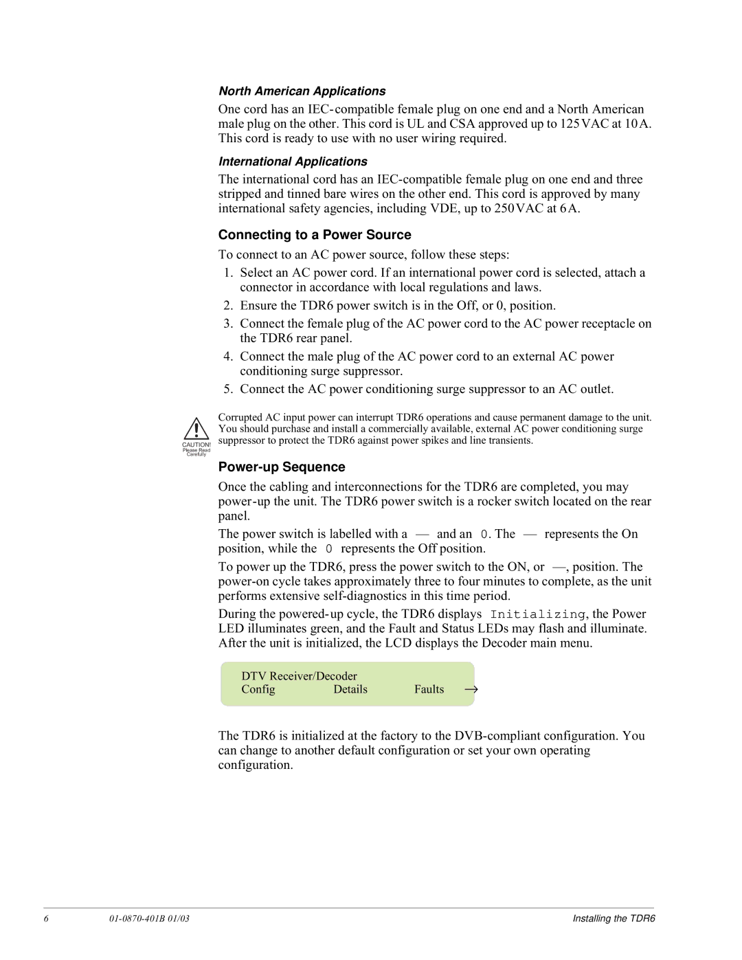
During the
DTV Receiver/Decoder |
| → | |
Config | Details | Faults | |
The TDR6 is initialized at the factory to the
6 |
| Installing the TDR6 |