Return to Section TOC
Return to Master TOC
TROUBLESHOOTING & REPAIR
MAIN TRANSFORMER REMOVAL & REPLACEMENT (continued)
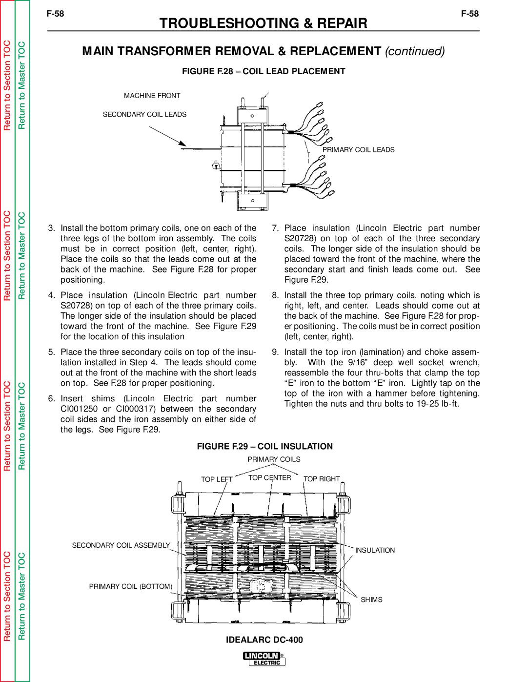
FIGURE F.28 – COIL LEAD PLACEMENT
MACHINE FRONT
SECONDARY COIL LEADS
PRIMARY COIL LEADS
Return to Section TOC
to Section TOC
Return to Master TOC
to Master TOC
3.Install the bottom primary coils, one on each of the three legs of the bottom iron assembly. The coils must be in correct position (left, center, right). Place the coils so that the leads come out at the back of the machine. See Figure F.28 for proper positioning.
4.Place insulation (Lincoln Electric part number S20728) on top of each of the three primary coils. The longer side of the insulation should be placed toward the front of the machine. See Figure F.29 for the location of this insulation
5.Place the three secondary coils on top of the insu- lation installed in Step 4. The leads should come out at the front of the machine with the short leads on top. See F.28 for proper positioning.
6.Insert shims (Lincoln Electric part number CI001250 or CI000317) between the secondary coil sides and the iron assembly on either side of the legs. See Figure F.29.
7.Place insulation (Lincoln Electric part number S20728) on top of each of the three secondary coils. The longer side of the insulation should be placed toward the front of the machine, where the secondary start and finish leads come out. See Figure F.29.
8.Install the three top primary coils, noting which is right, left, and center. Leads should come out at the back of the machine. See Figure F.28 for prop- er positioning. The coils must be in correct position (left, center, right).
9.Install the top iron (lamination) and choke assem- bly. With the 9/16” deep well socket wrench, reassemble the four