ACCESSORIES
Return to Section TOC
Return to Section TOC
Return to Master TOC
Return to Master TOC
5.Extend wire feeder control cable lead #21 so it can be connected directly to the work piece.
a.Make a bolted connection using AWG #14 or larger insulated wire. Tape the bolted connec- tion with insulating tape.
b.An
c.Keep the #21 lead electrically separate from the work cable circuit and connection.
d.Tape the #21 lead to work cable for ease of use.
6.Connect
NOTE: The connection diagram shown in Figure C.5 shows the electrode connected for positive polarity. To change polarity:
a.Set the Idealarc
b.Move the electrode cable to the negative
c.Move the work cable to the positive (+) output terminal.
d.Set the VOLTMETER toggle switch to negative
NOTE: For proper
7.Set the
CONNECTING THE
1.Disconnect main AC input power to the Idealarc
2.Set the Idealarc
(0) position.
3.Connect the electrode cable from the
NOTE: Welding cable must be sized for the cur- rent and duty cycle of the application.
4.Set the welder VOLTMETER switch to the desired polarity, either DC
5.Set the MODE switch to a CV (constant voltage) position.
6.Set the
Return to Section TOC
Return to Section TOC
Return to Master TOC
Return to Master TOC
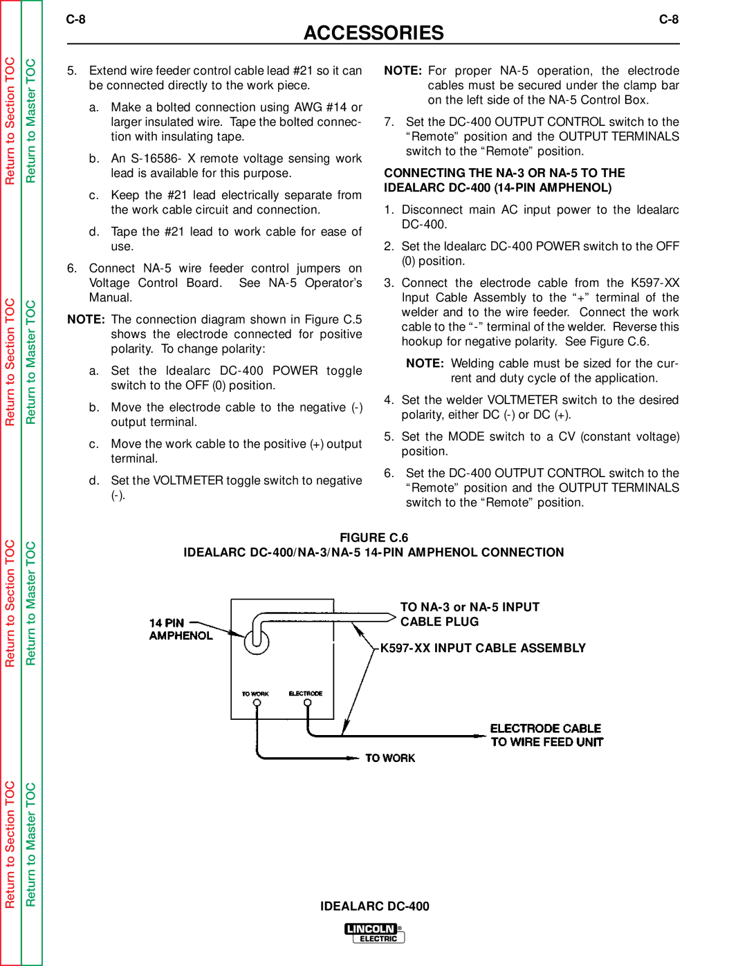
FIGURE C.6
IDEALARC DC-400/NA-3/NA-5 14-PIN AMPHENOL CONNECTION
TO NA-3 or NA-5 INPUT
CABLE PLUG
K597-XX INPUT CABLE ASSEMBLY
IDEALARC DC-400
LINCOLN ®
ELECTRIC