Return to Section TOC
Return to Section TOC
Return to Master TOC
Return to Master TOC
TROUBLESHOOTING & REPAIR
MAIN TRANSFORMER REMOVAL & REPLACEMENT (continued)
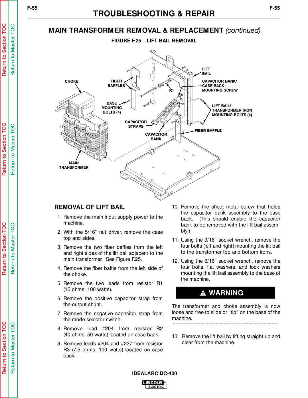
FIGURE F.25 – LIFT BAIL REMOVAL
Return to Section TOC
Return to Section TOC
Return to Master TOC
Return to Master TOC
REMOVAL OF LIFT BAIL
1.Remove the main input supply power to the machine.
2.With the 5/16” nut driver, remove the case top and sides.
3.Remove the two fiber baffles from the left and right sides of the lift bail adjacent to the main transformer. See Figure F.25.
4.Remove the fiber baffle from the left side of the choke.
5.Remove the two leads from resistor R1 (15 ohms, 100 watts).
6.Remove the positive capacitor strap from the output shunt.
7.Remove the negative capacitor strap from the mode selector switch.
8.Remove lead #204 from resistor R2 (40 ohms, 50 watts) located on case back.
9.Remove leads #204 and #227 from resistor R3 (7.5 ohms, 100 watts) located on case back.
10.Remove the sheet metal screw that holds the capacitor bank assembly to the case back. (This should enable the capacitor bank to be removed with the lift bail assem- bly.)
11.Using the 9/16” socket wrench, remove the four bolts (left and right) mounting the lift bail to the transformer top and bottom irons.
12.Using the 9/16” socket wrench, remove the four bolts, flat washers, and lock washers mounting the lift bail assembly to the base of the machine.
![]() WARNING
WARNING
The transformer and choke assembly is now loose and free to slide or “tip” on the base of the machine.
13.Remove the lift bail by lifting straight up and clear from the machine.
IDEALARC
LINCOLN ®
ELECTRIC