Return to Section TOC
Return to Section TOC
TOC
Return to Master TOC
Return to Master TOC
TOC
OPERATION
CONTROLS AND SETTINGS
All operator controls and settings are located on the case front assembly. See Figure B.1 for their loca- tions.
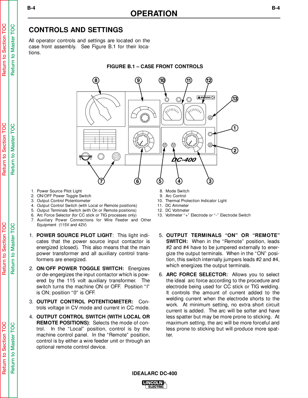
FIGURE B.1 – CASE FRONT CONTROLS
1. | Power Source Pilot Light | 8. | Mode Switch |
2. | ON/OFF Power Toggle Switch | 9. | Arc Control |
3. | Output Control Potentiometer | 10. | Thermal Protection Indicator Light |
4. | Output Control Switch (with Local or Remote positions) | 11. | DC Ammeter |
5. | Output Terminals Switch (with On or Remote positions) | 12. | DC Voltmeter |
6. | Arc Force Selector (for CC stick or TIG processes only) | 13. | Voltmeter “+” Electrode or |
7.Auxiliary Power Connections for Wire Feeder and Other Equipment (115V and 42V)
Return to Section
Return to Section TOC
Return to Master
Return to Master TOC
1.POWER SOURCE PILOT LIGHT: This light indi- cates that the power source input contactor is energized (closed). This also means that the main power transformer and all auxiliary control trans- formers are energized.
2.ON/OFF POWER TOGGLE SWITCH: Energizes or
3.OUTPUT CONTROL POTENTIOMETER: Con- trols voltage in CV mode and current in CC mode.
4.OUTPUT CONTROL SWITCH (WITH LOCAL OR REMOTE POSITIONS): Selects the mode of con- trol. In the “Local” position, control is by the machine control panel. In the “Remote” position, control is by either a wire feeder unit or through an optional remote control device.
5.OUTPUT TERMINALS “ON” OR “REMOTE” SWITCH: When in the “Remote” position, leads #2 and #4 have to be jumpered externally to ener- gize the output terminals. When in the “ON” posi- tion, this switch internally jumpers leads #2 and #4, which energizes the output terminals.
6.ARC FORCE SELECTOR: Allows you to select the ideal arc force according to the procedure and electrode being used for CC stick or TIG welding. It controls the amount of current added to the welding current when the electrode shorts to the work. At minimum setting, no extra short circuit current is added. The arc will be softer and have less spatter but may be more prone to sticking. At maximum setting, the arc will be more forceful and less prone to sticking but will produce more spat- ter.
IDEALARC
LINCOLN ®
ELECTRIC