Section TOC
Master TOC
THEORY OF OPERATION
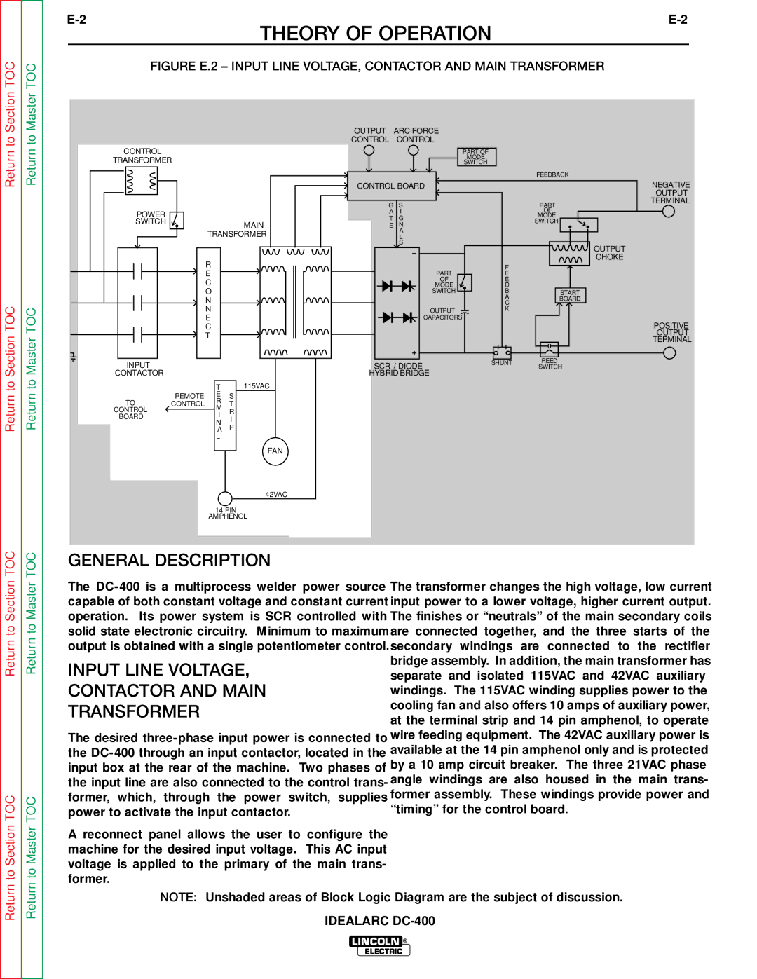
FIGURE E.2 – INPUT LINE VOLTAGE, CONTACTOR AND MAIN TRANSFORMER
Return to
Return to Section TOC
Return to
Return to Master TOC
CONTROL
TRANSFORMER
POWER |
|
|
|
SWITCH |
|
| MAIN |
|
|
| |
|
| TRANSFORMER | |
|
| R |
|
|
| E |
|
|
| C |
|
|
| O |
|
|
| N |
|
|
| N |
|
|
| E |
|
|
| C |
|
|
| T |
|
INPUT |
|
|
|
CONTACTOR |
|
|
|
|
| T | 115VAC |
| REMOTE | E | S |
TO | CONTROL | R | T |
CONTROL |
| M | R |
BOARD |
| I | I |
|
| N | |
|
| P | |
|
| A | |
|
| L |
|
|
|
| FAN |
|
|
| 42VAC |
|
| 14 PIN | |
|
| AMPHENOL | |
OUTPUT | ARC FORCE |
|
|
|
CONTROL | CONTROL |
|
|
|
| PART OF |
|
|
|
| MODE |
|
|
|
| SWITCH |
|
|
|
|
|
| FEEDBACK |
|
CONTROL BOARD |
|
| NEGATIVE | |
|
|
|
| OUTPUT |
G | S |
| PART | TERMINAL |
|
| |||
A | I |
| OF |
|
T | G |
| MODE |
|
| SWITCH |
| ||
E | N |
|
| |
|
|
| ||
| A |
|
|
|
| L |
|
|
|
| S |
|
| OUTPUT |
|
|
|
| |
|
|
|
| CHOKE |
|
| F |
|
|
| PART | E |
|
|
| OF | E |
|
|
| MODE | D |
|
|
| SWITCH | B | START |
|
|
| A | BOARD |
|
|
| C |
| |
|
|
|
| |
| OUTPUT | K |
|
|
|
|
|
| |
| CAPACITORS |
|
|
|
|
|
|
| POSITIVE |
|
|
|
| OUTPUT |
|
|
|
| TERMINAL |
SCR / DIODE | SHUNT | REED |
| |
SWITCH |
| |||
|
| |||
HYBRID BRIDGE |
|
|
| |
Return to Section TOC
Return to Section TOC
Return to Master TOC
Return to Master TOC
GENERAL DESCRIPTION
The | The transformer changes the high voltage, low current | |
capable of both constant voltage and constant current | input power to a lower voltage, higher current output. | |
operation. Its power system is SCR controlled with | The finishes or “neutrals” of the main secondary coils | |
solid state electronic circuitry. Minimum to maximum | are connected together, and the three starts of the | |
output is obtained with a single potentiometer control. | secondary windings are connected to the rectifier | |
INPUT LINE VOLTAGE, | bridge assembly. In addition, the main transformer has | |
separate and isolated 115VAC and 42VAC auxiliary | ||
CONTACTOR AND MAIN | windings. The 115VAC winding supplies power to the | |
TRANSFORMER | cooling fan and also offers 10 amps of auxiliary power, | |
at the terminal strip and 14 pin amphenol, to operate | ||
| ||
The desired | wire feeding equipment. The 42VAC auxiliary power is | |
the | available at the 14 pin amphenol only and is protected | |
input box at the rear of the machine. Two phases of | by a 10 amp circuit breaker. The three 21VAC phase | |
the input line are also connected to the control trans- | angle windings are also housed in the main trans- | |
former, which, through the power switch, supplies | former assembly. These windings provide power and | |
power to activate the input contactor. | “timing” for the control board. |
A reconnect panel allows the user to configure the machine for the desired input voltage. This AC input voltage is applied to the primary of the main trans- former.
NOTE: Unshaded areas of Block Logic Diagram are the subject of discussion.
IDEALARC
LINCOLN ®
ELECTRIC