Return to Section TOC
Return to Section TOC
Return to Section TOC
Return to Section TOC
Return to Master TOC
Return to Master TOC
Return to Master TOC
Return to Master TOC
TROUBLESHOOTING & REPAIR
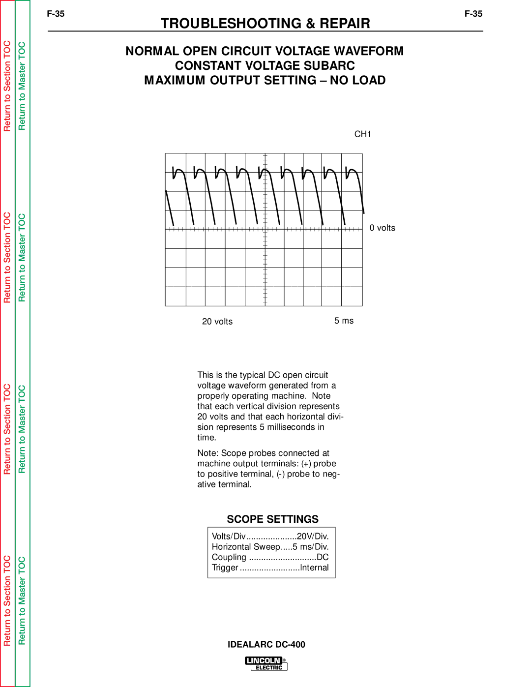
NORMAL OPEN CIRCUIT VOLTAGE WAVEFORM
CONSTANT VOLTAGE SUBARC
MAXIMUM OUTPUT SETTING – NO LOAD
CH1
0 volts
20 volts | 5 ms |
This is the typical DC open circuit voltage waveform generated from a properly operating machine. Note that each vertical division represents 20 volts and that each horizontal divi- sion represents 5 milliseconds in time.
Note: Scope probes connected at
machine output terminals: (+) probe to positive terminal,
SCOPE SETTINGS
Volts/Div | 20V/Div. |
Horizontal Sweep | 5 ms/Div. |
Coupling | DC |
Trigger | Internal |
|
|
IDEALARC
LINCOLN ®
ELECTRIC