Return to Section TOC
Return to Section TOC
Return to Section TOC
Return to Section TOC
Return to Master TOC
Return to Master TOC
Return to Master TOC
Return to Master TOC
ELECTRICAL DIAGRAMS | ||
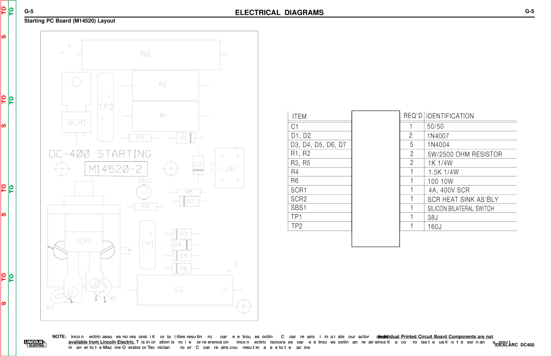
Starting PC Board (M14520) Layout |
|
|
| ITEM | PART NO. | REQ'D |
| IDENTIFICATION |
|
| ||||
|
|
|
|
|
|
| C1 | 1 |
| 50/50 | |
|
|
|
|
|
|
| D1, D2 | 2 |
| 1N4007 | |
| D3, D4, D5, D6, D7 | 5 |
| 1N4004 | |
| R1, R2 | 2 |
| 5W/2500 OHM RESISTOR | |
| R3, R5 |
| 2 |
| 1K 1/4W |
| R4 | 1 |
| 1.5K 1/4W | |
| R6 | 1 |
| 100 10W | |
| SCR1 | 1 |
| 4A, 400V SCR | |
| SCR2 | 1 |
| SCR HEAT SINK AS'BLY | |
|
| ||||
| SBS1 | 1 |
| SILICON BILATERAL SWITCH | |
| TP1 | 1 |
| 38J | |
| TP2 | 1 |
| 160J | |
|
|
|
|
|
|
|
|
|
|
|
|
NOTE: Lincoln Electric assumes no responsibility for liablilities resulting from board level troubleshooting. PC Board repairs will invalidate your factory warranty. Individual Printed Circuit Board Components are not
available from Lincoln Electric. This information is provided for reference only. Lincoln Electric discourages board level troubleshooting and repair since it may compromise the quality of the design and may result IDEALARC DC400 in danger to the Machine Operator or Technician. Improper PC board repairs could result in damage to the machine.