Return to Section TOC
Return to Master TOC
TROUBLESHOOTING & REPAIR
ACTIVE SCR TEST (continued)
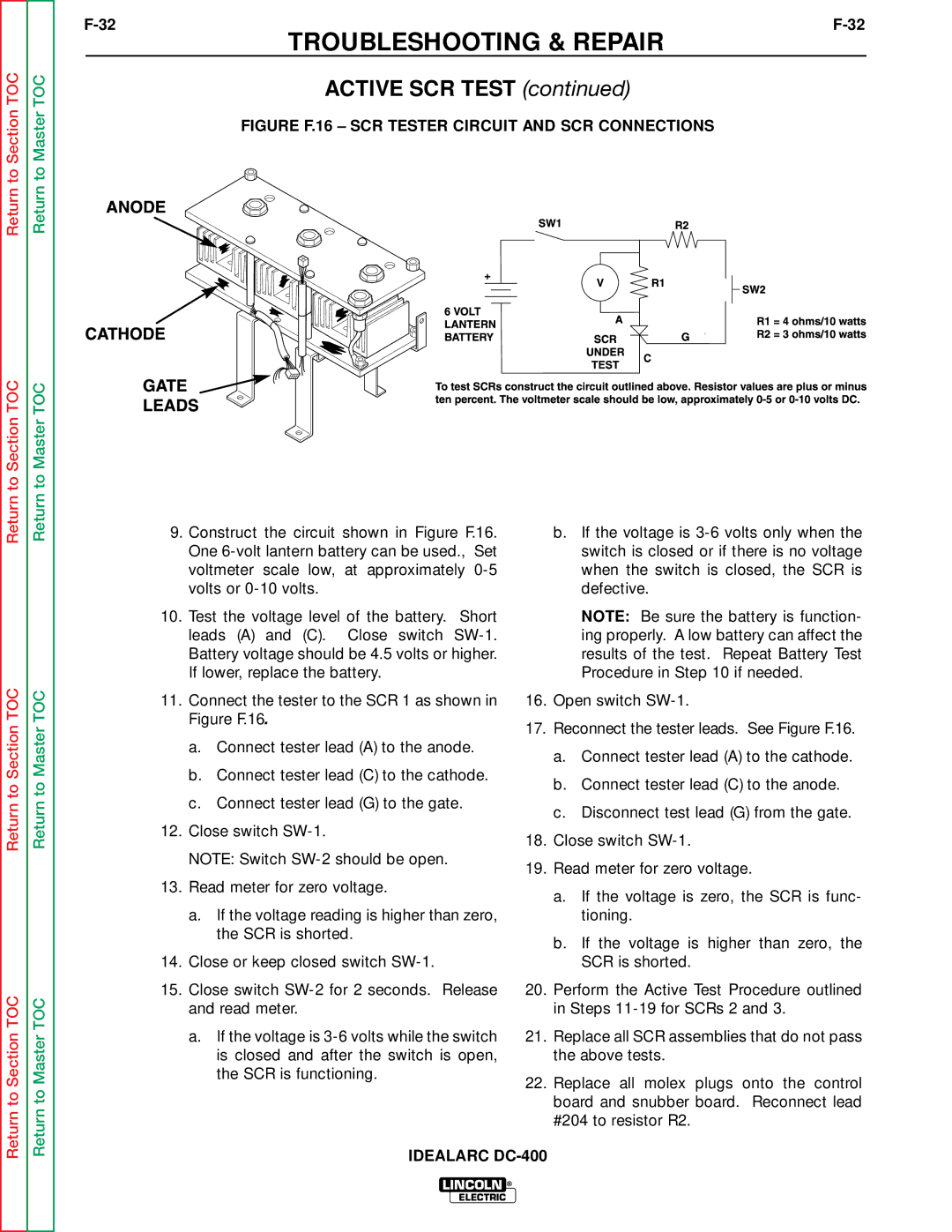
FIGURE F.16 – SCR TESTER CIRCUIT AND SCR CONNECTIONS
Return to Section TOC
Return to Section TOC
Return to Section TOC
Return to Master TOC
Return to Master TOC
Return to Master TOC
9.Construct the circuit shown in Figure F.16. One
10.Test the voltage level of the battery. Short leads (A) and (C). Close switch
11.Connect the tester to the SCR 1 as shown in Figure F.16.
a.Connect tester lead (A) to the anode.
b.Connect tester lead (C) to the cathode.
c.Connect tester lead (G) to the gate.
12.Close switch
NOTE: Switch
13.Read meter for zero voltage.
a.If the voltage reading is higher than zero, the SCR is shorted.
14.Close or keep closed switch
15.Close switch
a.If the voltage is
b.If the voltage is
NOTE: Be sure the battery is function- ing properly. A low battery can affect the results of the test. Repeat Battery Test Procedure in Step 10 if needed.
16.Open switch
17.Reconnect the tester leads. See Figure F.16.
a.Connect tester lead (A) to the cathode.
b.Connect tester lead (C) to the anode.
c.Disconnect test lead (G) from the gate.
18.Close switch
19.Read meter for zero voltage.
a.If the voltage is zero, the SCR is func- tioning.
b.If the voltage is higher than zero, the SCR is shorted.
20.Perform the Active Test Procedure outlined in Steps
21.Replace all SCR assemblies that do not pass the above tests.
22.Replace all molex plugs onto the control board and snubber board. Reconnect lead #204 to resistor R2.
IDEALARC
LINCOLN ®
ELECTRIC