User Guide for Voice/IP Gateways
S000384A
User Guide
Contents
Contents MultiVOIP User Guide
MultiVOIP User Guide Contents
Overview
About This Manual
MultiVOIP Product Family
MultiVOIP MVP2410 LEDs
Introduction to TI MultiVOIPs MVP2410 & MVP24-48
Overview MultiVOIP User Guide
MultiVOIP User Guide Overview
Overview MultiVOIP User Guide
MultiVOIP User Guide Overview
Overview MultiVOIP User Guide
MVP2410 LEDs
T1 Front Panel LEDs
LED Name Description
MultiVOIP MVP3010 Chassis
Introduction to EI MultiVOIPs MVP3010 & MVP30-60
Overview MultiVOIP User Guide
MultiVOIP User Guide Overview
Overview MultiVOIP User Guide
MultiVOIP User Guide Overview
Overview MultiVOIP User Guide
MVP3010 LEDs
E1 Front Panel LEDs
MVP3010 Front Panel LED Definitions
E1 LED Descriptions
Specs for Digital T1 MultiVOIP Units
Specifications
Specs for Digital E1 MultiVOIP Units
Digital E1 MultiVOIP Specifications
Related Documentation
Installation at a Glance
Quick Start Instructions
MultiVOIP User Guide Quick Start Instructions
Mechanical Installation and Cabling
Lithium Battery Caution
Safety Warnings
Safety Warnings Telecom
Introduction
Unpacking the MVP2410/3010
Unpacking Your MultiVOIP
Rack-Mounting
Rack Mounting Instructions
Safety Recommendations for Rack Installations
Bracket Attachment for Rack Mounting
Inch Rack Enclosure Mounting Procedure
Cabling
Cabling Procedure
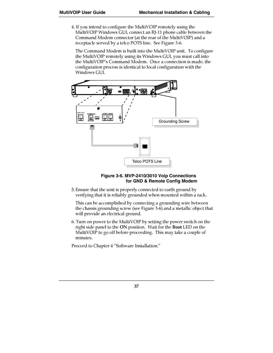
MVP-2410/3010 Voip Connections for GND & Remote Config Modem
Software Installation
Loading MultiVOIP Software onto the PC
Technical Configuration T1/E1 MultiVOIP User Guide
MultiVOIP User Guide Mechanical Installation & Cabling
Technical Configuration T1/E1 MultiVOIP User Guide
MultiVOIP User Guide Mechanical Installation & Cabling
Technical Configuration T1/E1 MultiVOIP User Guide
MultiVOIP User Guide Mechanical Installation & Cabling
Un-Installing the MultiVOIP Configuration Software
MultiVOIP User Guide Mechanical Installation & Cabling
Completion screen will appear Click Finish
Technical Configuration
Configuring the MultiVOIP
MultiVOIP User Guide Technical Configuration
Technical Configuration MultiVOIP User Guide
Pre-Requisites
Local Configuration
IP Parameters
T1 Telephony Parameters for MVP2410
E1 Telephony Parameters for MVP3010
Smtp Parameters for email call log reporting
Config Info CheckList
Local Configuration Procedure Summary
Local Configuration Procedure Detailed
MultiVOIP User Guide Technical Configuration
Technical Configuration MultiVOIP User Guide
Ctrl + G
Solving Common Connection Problems
Technical Configuration MultiVOIP User Guide
Pulldown Icon Shortcut Sidebar
Ctrl + Alt +
Technical Configuration MultiVOIP User Guide
Background Bulk transfers and other
Important business
IP Parameter fields
Value is used to prioritize call setup IP packets
Bits =
Type of Service or TOS field
DNS Parameter fields
TDM Routing Option Parameter Fields
Technical Configuration MultiVOIP User Guide
Ctrl + H
Technical Configuration MultiVOIP User Guide
MultiVOIP User Guide Technical Configuration
Dtmf Parameters
RFC2833 method. Uses an RTP
Dtmf
Jitter Value Default =
726, @
711 a/u
727, @
723.1 @
Silence
Forward Error Correction enables
Auto Call AutoCall
Generate
Phone
Jitter
Optimization Factor
Modem Relay
Call Duration defines
Automatic Disconnection
Consecutive Packets Lost defines
Ctrl + T
Technical Configuration MultiVOIP User Guide
MultiVOIP User Guide Technical Configuration
Frame Format of MultiVOIP
RING-ON, RING-OFF
FXS Ground Start Supervision Parameters
Parameters Field Name Values Description
Isdn
Numbering Details Parameters
Parameters
Refers to length of cable
Pattern
MultiVOIP User Guide Technical Configuration
100
MFR2 ANI
101
102
103
104
General E1/E1/ISDN Parameters
105
106
107
108
Pulldown Shortcut Sidebar
109
IP address of the GateKeeper
110
111
Field Name Values Description
112
113
114
115
Field Name Values & Description
116
117
118
Registrar
119
Address
120
About SPP Proxy/NAT Device Parameters
121
Ctrl + M
122
Trap Manager Parameters
Snmp Parameter Definitions Field Name Values Description
123
124
Ctrl + R
125
126
Regional Parameter Definitions Field Name Values Description
Standard Tones fields
127
Standard Tones fields cont’d
128
MVP810ST
129
Technical Configuration MultiVOIP User Guide
131
Tone Pair Values
132
133
Ctrl + Alt + S
134
Smtp Parameters Definitions Field Name Values Description
Mail Criteria
135
136
Custom Fields Definitions Description
Matched
137
Details
138
139
140
Ctrl + Alt + L
141
Messages
142
143
144
Ctrl + Alt +H
145
146
147
Or #
148
Its Statistics Call Progress screen
Party, Busy Party, and Connected
149
Statistics Call Progress screen
Allowed Name Type, and Omaha
150
151
Supplementary Services screen
Field of the Statistics Call Progress
Identification has been enabled, Busy
152
An Allowed Name Type,
Supplementary Services
153
154
155
156
Ctrl + Alt + Sft + VH
157
Stun
158
Accessing Radius Parameters Pulldown Icon Shortcut Sidebar
159
160
Retransmissions field
161
162
Sent
163
164
165
Ctrl + Alt +Y
166
167
168
169
170
T1 Phonebook Configuration
T1 Versus E1 Telephony Environments
Configuring T1 NAM Telephony MultiVOIP Phonebooks
171
172
T1 Phonebook Configuration MultiVOIP User Guide
173
Phonebook Icons Description
174
Alt + Alt + O
175
Select Outbound Phone Book/List Entries
176
Add/Edit Outbound PhoneBook screen appears
Device is used . If Any
177
178
This field currently disabled
179
SIP Fields
180
SPP Fields
181
182
183
PBX
184
Add/Edit Inbound PhoneBook screen appears 185
186
When no external routing device is used. If
187
Destination
188
Sites, All-T1 Example
T1 Phonebook Examples
189
PBX
190
191
192
193
194
195
Configuring Mixed Digital/Analog Voip Systems
196
197
Phone Book for Series I Analog Voip Host Unit Site B
198
199
Voip
200
201
202
203
421
Call Completion Summaries
Site a calling Site C, Method
Site C calling Site a
205
Site D calling Site C
206
Site D calling Site F
207
Variations in PBX Characteristics
208
E1 Phonebook Configuration
E1-Standard Inbound and Outbound MultiVOIP Phonebooks
E1 Versus T1 Telephony Environments
209
210
Free Calls One Voip Site to Another
211
Local Rate Calls Within Local Calling Area of Remote
United Kingdom
212
213
National Rate Calls Within Nation of Remote Voip Site
214
Inbound versus Outbound Phonebooks
215
216
217
218
Phonebook Configuration Procedure
219
220
221
222
223
Device is …
224
225
Select Inbound PhoneBook/List Entries 226
227
Add/Edit Inbound PhoneBook screen appears
228
When no external routing device is used . If
229
Call Forward Parameters
230
Sites, All-E1 Example
E1 Phonebook Examples
231
232
France Country Code
Rotterdam
010
233
234
PBX
235
236
237
238
Configuring Digital & Analog VOIPs in Same System
239
Phone Book for Analog Voip Host Unit Site B
240
241
Outbound Phone Book for MVP3010 Digital Voip Site D
242
Inbound Phone Book for MVP3010 Digital Voip Site D
243
244
245
Site C calling Site a
Site a calling Site C, Method
246
247
248
249
250
International Telephony Numbering Plan Resources
251
252
Operation and Maintenance
System Information screen
Operation and Maintenance
253
254
255
About Call Progress
Statistics Screens
Pulldown Icon Shortcut
256
257
258
Call Details
259
SC, FEC
260
Dtmf
261
262
Services Status
263
Correction. Forward Error
264
About Logs
265
266
Special Buttons
267
268
269
Cont’d From Details
270
271
About IP Statistics
272
Total Packets
UDP versus TCP
273
274
UDP
275
Rtcp
Pulldown Shortcut // Icon
About Link Management
276
277
278
279
280
281
282
283
284
285
286
Pulldown Shortcut
About Registered Gateway Details
287
288
289
290
About Alternate Server Statistics
291
292
293
Pulldown Shortcut/Icon
About Packetization Time
294
295
Packetization Ranges and Increments
296
MultiVOIP Program Menu
MultiVoip Program Menu Items
Menu Selection Description
297
298
Download CAS Protocol
Configuration Port Setup
Configuration Option
299
Obtaining Updated Firmware
Date and Time Setup
300
301
302
303
304
Implementing a Software Upgrade
305
Downloading Firmware
306
307
308
Downloading CAS Protocol
309
310
Downloading Factory Defaults
311
312
313
Setting and Downloading User Defaults
314
315
316
Setting a Password Windows GUI
317
318
319
320
Setting a Password Web Browser GUI
321
Un-Installing the MultiVOIP Software
322
323
Upgrading Software
324
FTP Server File Transfers Downloads
325
326
327
328
329
330
331
332
333
334
Web Browser Interface
335
336
337
338
339
340
SysLog Server Functions
341
Operation and Maintenance MultiVOIP User Guide
343
Warranty, Service, and Tech Support
Repair Procedures for U.S. and Canadian Customers
Limited Warranty
344
345
MultiVOIP User Guide Warranty, Service, & Tech Support
Contacting Technical Support
Technical Support
Country By E-mail By telephone
346
347
Regulatory Information
FCC Declaration
EMC, Safety, and R&TTE Directive Compliance
348
FCC Part 68 Telecom
Industry Canada
349
350
Canadian Limitations Notice
351
Weee Statement
352
Appendix a Cable Pinouts
Ethernet Connector
Command Cable
Appendix a Cable Pinouts
353
Voice/Fax Channel Connectors
T1/E1 Connector
T1/E1 Connector
354
355
356
Isdn BRI RJ-45 Pinout Information
357
Isdn Interfaces ST and U
358
Appendix B TCP/UDP Port Assignments
Port Number Assignment List
Well Known Port Numbers
359
360
361
Installation Instructions for MVP428 Upgrade Card
362
Channel Analog Expansion Card MultiVOIP User Guide
363
Screw locations 2 at phone-jack edge of board
364
Pin connectors
365
366
Index
367
368
369
256
370
371
T1/ISDN
372
See
373
374
375
68, 69, 70
376
FRF11
377
269
378
Version 4 Parameters
379
ISDN-PRI
380
PRI
381
Snmp
382
383
384
385
386
387
Safety Warnings Telecom
388
389
152, 153
390
391
Telecom safety warnings
392
393
394
395