Chapter 4 | VisuaLink 128/384 User Guide |
STEP | ACTION |
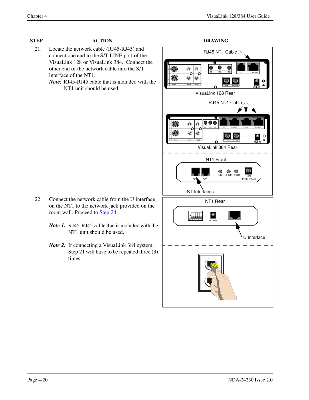
21.Locate the network cable
Note:
22.Connect the network cable from the U interface on the NT1 to the network jack provided on the room wall. Proceed to Step 24.
Note 1:
Note 2: If connecting a VisuaLink 384 system, Step 21 will have to be repeated three (3) times.
| DRAWING |
|
| |||
| RJ45 NT1 Cable |
|
| |||
+ |
| + |
|
| + | |
O |
|
|
|
|
| |
U |
|
|
|
|
| |
T | MIC1 | MIC2 | MIC3 | TEL | S/T LINE | |
+ | ||||||
+ |
|
|
|
| ||
I |
|
|
|
|
| |
N |
|
|
|
|
| |
+
VIDEO2 | VIDEO1 | AUDIO |
+ | Serial1 | Serial2/RMT | DC IN 5V | ||
|
| - |
| + | |
VisuaLink 128 Rear
RJ45 NT1 Cable
+ |
| + |
|
|
| + |
O |
|
|
|
|
|
|
U |
|
|
|
|
|
|
T |
|
| TEL | S/T LINE 1 | S/T LINE 2 | S/T LINE 3 |
MIC1 | MIC2 | MIC3 |
+ | + |
I |
|
|
|
|
|
N |
|
|
|
|
|
|
|
|
|
| + |
VIDEO2 | VIDEO1 | AUDIO | Serial2/RMT | DC IN 5V | |
|
| Serial1 | |||
|
| + |
| - | + |
VisuaLink 384 Rear
NT1 Front
|
| DIN | |
S/T | S/T |
| INTERFACE |
ST Interfaces |
| |||
|
|
| NT1 Rear |
|
ON | 2 3 4 | 5 |
|
|
1 | POWER |
| ||
|
|
| U | |
|
|
|
| |
U Interface
Page |