NEC LC1400 manual Option Boards, Installation Considerations, PCI and ISA Slot Locations

Models: LC1400

1 200
Download 200 pages 1.21 Kb
Page 99
Image 99

Option Boards

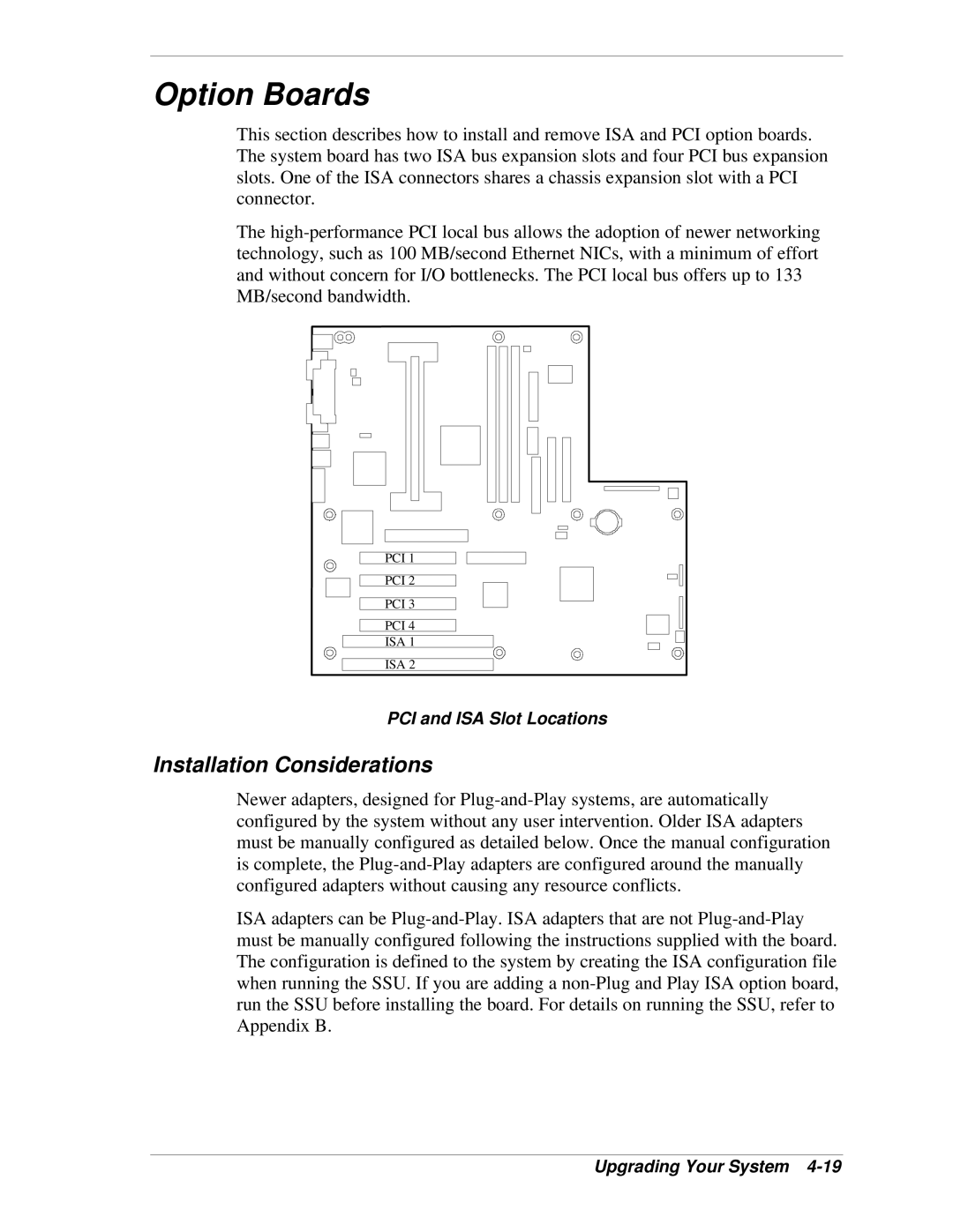
This section describes how to install and remove ISA and PCI option boards. The system board has two ISA bus expansion slots and four PCI bus expansion slots. One of the ISA connectors shares a chassis expansion slot with a PCI connector.

The high-performance PCI local bus allows the adoption of newer networking technology, such as 100 MB/second Ethernet NICs, with a minimum of effort and without concern for I/O bottlenecks. The PCI local bus offers up to 133 MB/second bandwidth.

PCI 1

PCI 2

PCI 3

PCI 4

ISA 1

ISA 2

PCI and ISA Slot Locations

Installation Considerations

Newer adapters, designed for Plug-and-Play systems, are automatically configured by the system without any user intervention. Older ISA adapters must be manually configured as detailed below. Once the manual configuration is complete, the Plug-and-Play adapters are configured around the manually configured adapters without causing any resource conflicts.

ISA adapters can be Plug-and-Play. ISA adapters that are not Plug-and-Play must be manually configured following the instructions supplied with the board. The configuration is defined to the system by creating the ISA configuration file when running the SSU. If you are adding a non-Plug and Play ISA option board, run the SSU before installing the board. For details on running the SSU, refer to Appendix B.

Upgrading Your System 4-19

Page 99
Image 99
NEC LC1400 manual Option Boards, Installation Considerations, PCI and ISA Slot Locations