Sheet 11/55
Termination of Cables on MDF
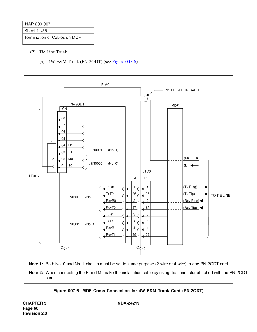
(2) | Tie Line Trunk |
|
|
|
|
|
| |
| (a) 4W E&M Trunk |
|
|
| ||||
|
|
| PIM0 |
|
|
|
| |
|
|
|
|
|
|
| INSTALLATION CABLE |
|
|
|
|
|
|
| MDF |
| |
| CN1 |
|
|
|
|
| ||
|
|
|
|
|
|
| ||
| 08 |
|
|
|
|
|
|
|
| 07 |
|
|
|
|
|
|
|
| 06 |
|
|
|
|
|
|
|
| 05 |
|
|
|
|
|
|
|
| J |
|
|
|
|
|
|
|
| 04 | M1 |
|
|
|
|
|
|
| 03 | E1 | LEN0001 | (No. 1) |
|
|
|
|
|
|
|
|
|
|
| ||
| 02 | M0 |
|
|
|
| (M) |
|
|
|
|
|
|
|
| ||
| 01 | E0 | LEN0000 | (No. 0) |
|
| (E) |
|
|
|
|
|
|
| |||
|
|
|
|
|
| LTC0 |
|
|
LT01 |
|
|
|
| J | P |
|
|
|
|
|
|
|
|
| ||
|
|
|
| TxR0 | 1 | 1 | (Tx Ring) |
|
|
| LEN0000 | (No. 0) | TxT0 | 26 | 26 | (Tx Tip) | TO TIE LINE |
|
|
|
|
|
| |||
|
| RcvR0 | 2 | 2 | (Rcv Ring) |
| ||
|
|
|
|
| ||||
|
|
|
| RcvT0 | 27 | 27 | (Rcv Tip) |
|
|
|
|
| TxR1 | 3 | 3 |
|
|
|
| LEN0001 | (No. 1) | TxT1 | 28 | 28 |
|
|
|
| RcvR1 | 4 | 4 |
|
| ||
|
|
|
|
|
| |||
|
|
|
| RcvT1 | 29 | 29 |
|
|
Note 1: Both No. 0 and No. 1 circuits must be set to same purpose
Note 2: When connecting the E and M, make the installation cable by using the connector attached with the
Figure | MDF Cross Connection for 4W E&M Trunk Card |
CHAPTER 3 | |
Page 60 |
|
Revision 2.0 |
|