3. FUNCTIONAL OUTLINE OF EQUIPMENT
This section explains the functional outline of the equipment (modules, installation hardware, circuit cards) used in the PBX.
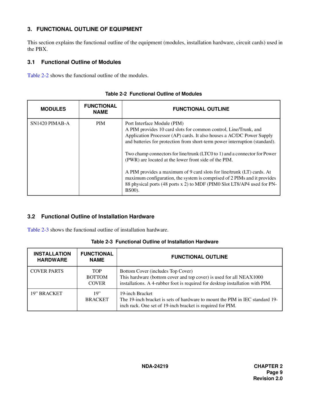
3.1Functional Outline of Modules
Table 2-2 shows the functional outline of the modules.
| Table | ||
|
|
| |
MODULES | FUNCTIONAL | FUNCTIONAL OUTLINE | |
NAME | |||
|
| ||
|
|
| |
SN1420 | PIM | Port Interface Module (PIM) | |
|
| A PIM provides 10 card slots for common control, Line/Trunk, and | |
|
| Application Processor (AP) cards. It also houses a AC/DC Power Supply | |
|
| and batteries for protection from | |
|
| Two champ connectors for line/trunk (LTC0 to 1) and a connector for Power | |
|
| (PWR) are located at the lower front side of the PIM. | |
|
| A PIM provides a maximum of 9 card slots for line/trunk (LT) cards. At | |
|
| maximum configuration, the system is comprised of 2 PIMs and it provides | |
|
| 88 physical ports (48 ports x 2) to MDF (PIM0 Slot LT8/AP4 used for PN- | |
|
| BS00). | |
|
|
| |
3.2Functional Outline of Installation Hardware
Table 2-3 shows the functional outline of installation hardware.
| Table | Functional Outline of Installation Hardware | |
|
|
|
|
INSTALLATION | FUNCTIONAL |
| FUNCTIONAL OUTLINE |
HARDWARE | NAME |
| |
|
| ||
|
|
|
|
COVER PARTS | TOP |
| Bottom Cover (includes Top Cover) |
| BOTTOM |
| This hardware (bottom cover and top cover) is used for all NEAX1000 |
| COVER |
| installations. A |
|
|
|
|
19” BRACKET | 19” |
| |
| BRACKET |
| The |
|
|
| inch rack. One set of |
|
|
|
|
NDA-24219 CHAPTER 2
Page 9
Revision 2.0