Sheet 11/12
Installation of Main Equipment
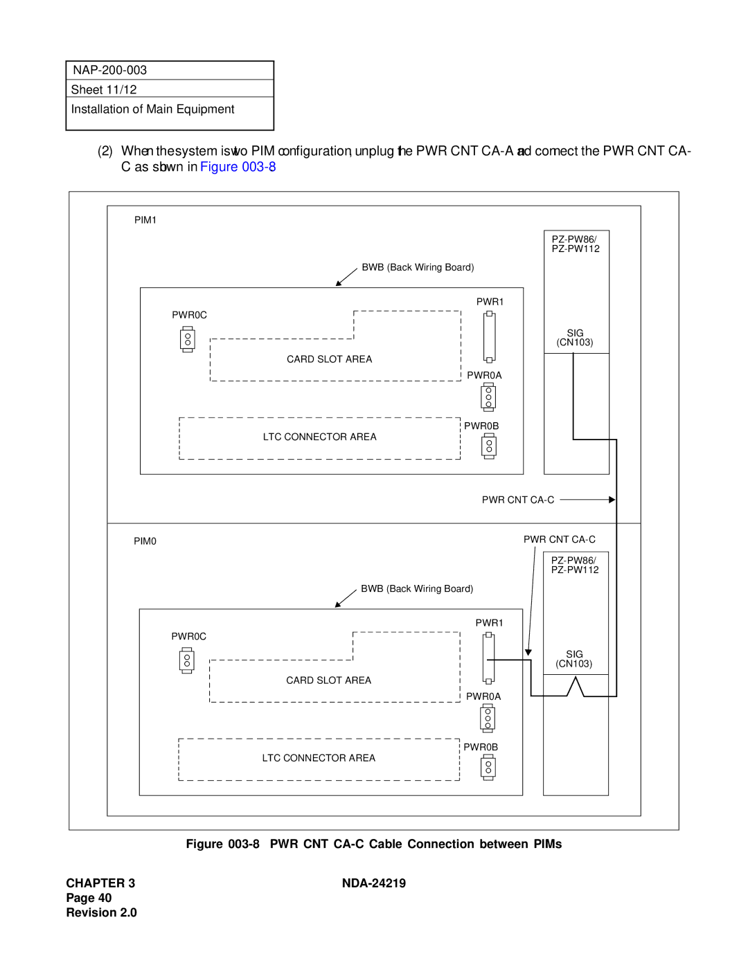
(2) When the system is two PIM configuration, unplug the PWR CNT
C as shown in Figure | |
PIM1 |
|
| |
| |
| BWB (Back Wiring Board) |
| PWR1 |
| PWR0C |
| SIG |
| (CN103) |
| CARD SLOT AREA |
| PWR0A |
| PWR0B |
| LTC CONNECTOR AREA |
| PWR CNT |
PIM0 | PWR CNT |
| |
| |
| BWB (Back Wiring Board) |
| PWR1 |
| PWR0C |
| SIG |
| (CN103) |
| CARD SLOT AREA |
| PWR0A |
| PWR0B |
| LTC CONNECTOR AREA |
Figure 003-8 PWR CNT CA-C Cable Connection between PIMs
CHAPTER 3 |
Page 40
Revision 2.0
