Northern UTA220/UTA220k DIP Switch Options, Pin Function, Location, default, Getting Started

Models: UTA220/UTA220k

1 187
Download 187 pages 21.16 Kb
Page 29
Image 29
Figure 3-5. V.35 Switch Location

Getting Started

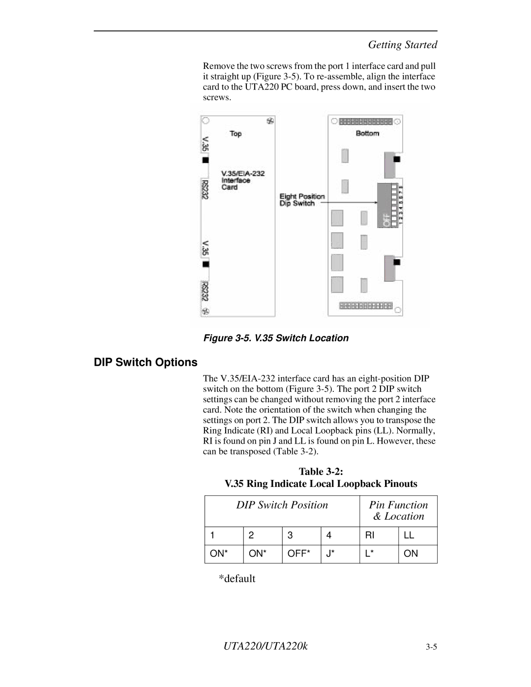
Remove the two screws from the port 1 interface card and pull it straight up (Figure 3-5). To re-assemble, align the interface card to the UTA220 PC board, press down, and insert the two screws.

Figure 3-5. V.35 Switch Location

DIP Switch Options

The V.35/EIA-232 interface card has an eight-position DIP switch on the bottom (Figure 3-5). The port 2 DIP switch settings can be changed without removing the port 2 interface card. Note the orientation of the switch when changing the settings on port 2. The DIP switch allows you to transpose the Ring Indicate (RI) and Local Loopback pins (LL). Normally, RI is found on pin J and LL is found on pin L. However, these can be transposed (Table 3-2).

Table 3-2:

V.35 Ring Indicate Local Loopback Pinouts


DIP Switch Position

Pin Function


& Location


1


2

3

4

RI

LL


ON*


ON*

OFF*

J*

L*

ON


*default

UTA220/UTA220k

3-5

Page 29
Image 29
Northern UTA220/UTA220k DIP Switch Options, Pin Function, Location, default, V.35 Ring Indicate Local Loopback Pinouts