Getting Started
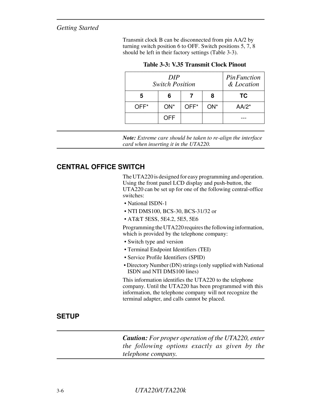
Transmit clock B can be disconnected from pin AA/2 by turning switch position 6 to OFF. Switch positions 5, 7, 8 should be left in their factory settings (Table
Table
|
|
| DIP |
|
| PinFunction |
|
| Switch Position |
| & Location | ||
|
|
|
|
|
| |
| 5 |
| 6 | 7 | 8 | TC |
|
|
|
|
|
|
|
| OFF* |
| ON* | OFF* | ON* | AA/2* |
|
|
|
|
|
|
|
|
|
| OFF |
|
| |
|
|
|
|
|
|
|
|
|
|
|
|
|
|
Note: Extreme care should be taken to
CENTRAL OFFICE SWITCH
The UTA220 is designed for easy programming and operation. Using the front panel LCD display and
•National
•NTI DMS100,
•AT&T 5ESS, 5E4.2, 5E5, 5E6
Programming the UTA220 requires the following information, which is provided by the telephone company:
•Switch type and version
•Terminal Endpoint Identifiers (TEI)
•Service Profile Identifiers (SPID)
•Directory Number (DN) strings (only supplied with National ISDN and NTI DMS100 lines)
This information identifies the UTA220 to the telephone company. Until the UTA220 has been programmed with this information, the telephone company will not recognize the terminal adapter, and calls cannot be placed.
SETUP
Caution: For proper operation of the UTA220, enter the following options exactly as given by the telephone company.
UTA220/UTA220k |