Using Socket Services by Manipulating Dedicated Control Bits | Section |
Continued from previous page. |
| ||
000003 | 000203 |
|
|
|
|
| MOV(21) |
|
|
| #0001 |
|
|
| D30018 |
|
|
| MOV(21) |
|
|
| #0064 |
|
|
| D30023 |
|
|
| MOV(21) |
|
|
| #8203 |
|
|
| D30024 |
|
|
| MOV(21) |
|
|
| #E800 |
|
|
| D30025 |
|
|
| MOV(21) |
|
|
| #0000 |
000003 | 000203 |
| D30026 |
|
| ||
|
|
| SET |
|
|
| 151904 |
|
|
| RSET |
|
|
| 000203 |
000003 | 000203 | 151904 |
|
|
| <>(305) | SET |
|
| D30027 | 000103 |
000003 | 000203 | #0000 |
|
151904 |
| ||
|
|
| RSET |
|
|
| 000003 |
|
|
| END(01) |
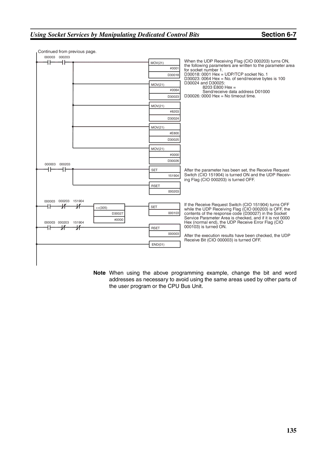
When the UDP Receiving Flag (CIO 000203) turns ON, the following parameters are written to the parameter area for socket number 1.
D30018: 0001 Hex = UDP/TCP socket No. 1
D30023: 0064 Hex = No. of send/receive bytes is 100
D30024 and D30025:
8203 E800 Hex =
Send/receive data address D01000 D30026: 0000 Hex = No timeout time.
After the parameter has been set, the Receive Request Switch (CIO 151904) is turned ON and the UDP Receiv- ing Flag (CIO 000203) is turned OFF.
If the Receive Request Switch (CIO 151904) turns OFF while the UDP Receiving Flag (CIO 000203) is OFF, the contents of the response code (D30027) in the Socket Service Parameter Area is checked, and if it is not 0000 Hex (normal end), the UDP Receive Error Flag (CIO 000103) is turned ON.
After the execution results have been checked, the UDP Receive Bit (CIO 000003) is turned OFF.
Note When using the above programming example, change the bit and word addresses as necessary to avoid using the same areas used by other parts of the user program or the CPU Bus Unit.