Using Socket Service Functions | Section |
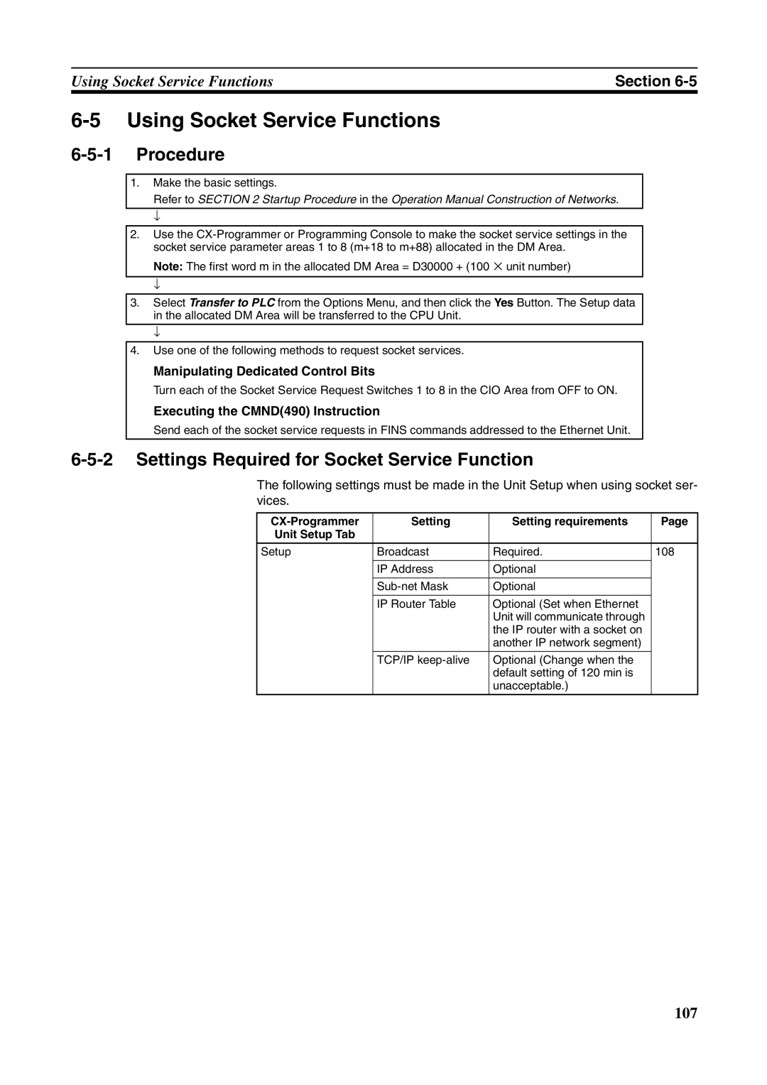
6-5 Using Socket Service Functions
6-5-1 Procedure
1.Make the basic settings.
Refer to SECTION 2 Startup Procedure in the Operation Manual Construction of Networks.
↓
2.Use the
Note: The first word m in the allocated DM Area = D30000 + (100 ⋅ unit number)
↓
3.Select Transfer to PLC from the Options Menu, and then click the Yes Button. The Setup data in the allocated DM Area will be transferred to the CPU Unit.
↓
4.Use one of the following methods to request socket services.
Manipulating Dedicated Control Bits
Turn each of the Socket Service Request Switches 1 to 8 in the CIO Area from OFF to ON.
Executing the CMND(490) Instruction
Send each of the socket service requests in FINS commands addressed to the Ethernet Unit.
6-5-2 Settings Required for Socket Service Function
The following settings must be made in the Unit Setup when using socket ser- vices.
| Setting | Setting requirements | Page |
Unit Setup Tab |
|
|
|
|
|
|
|
Setup | Broadcast | Required. | 108 |
|
|
|
|
| IP Address | Optional |
|
|
|
|
|
| Optional |
| |
|
|
|
|
| IP Router Table | Optional (Set when Ethernet |
|
|
| Unit will communicate through |
|
|
| the IP router with a socket on |
|
|
| another IP network segment) |
|
|
|
|
|
| TCP/IP | Optional (Change when the |
|
|
| default setting of 120 min is |
|
|
| unacceptable.) |
|
107
