Using Socket Services with CMND(490) | Section |
Data Flow
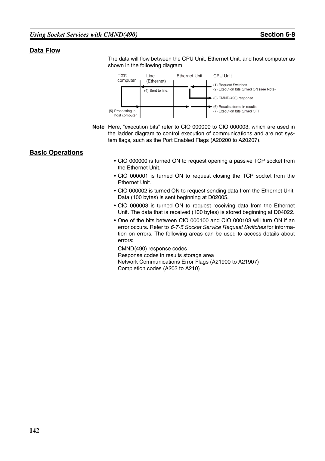
The data will flow between the CPU Unit, Ethernet Unit, and host computer as shown in the following diagram.
Host |
computer |
(5) Processing in |
host computer |
Line | Ethernet Unit |
|
| CPU Unit | |||||
(Ethernet) |
|
|
|
|
| (1) | Request Switches | ||
|
|
|
|
| |||||
|
|
|
|
|
| ||||
(4) Sent to line. |
|
|
|
|
|
|
| (2) | Execution bits turned ON (see Note) |
|
|
|
|
|
|
| |||
|
|
|
|
|
|
|
|
| |
|
|
|
|
|
|
| (3) | CMND(490) response | |
|
|
|
|
|
|
| |||
|
|
|
|
|
|
| (6) | Results stored in results | |
|
|
|
|
|
|
| |||
|
|
|
|
|
| (7) | Execution bits turned OFF | ||
|
|
|
|
|
|
|
|
|
|
Note Here, “execution bits” refer to CIO 000000 to CIO 000003, which are used in the ladder diagram to control execution of communications and are not sys- tem flags, such as the Port Enabled Flags (A20200 to A20207).
Basic Operations
•CIO 000000 is turned ON to request opening a passive TCP socket from the Ethernet Unit.
•CIO 000001 is turned ON to request closing the TCP socket from the Ethernet Unit.
•CIO 000002 is turned ON to request sending data from the Ethernet Unit. Data (100 bytes) is sent beginning at D02005.
•CIO 000003 is turned ON to request receiving data from the Ethernet Unit. The data that is received (100 bytes) is stored beginning at D04022.
•One of the bits between CIO 000100 and CIO 000103 will turn ON if an error occurs. Refer to
CMND(490) response codes Response codes in results storage area
Network Communications Error Flags (A21900 to A21907) Completion codes (A203 to A210)
142