FINS/UDP Method | Section |
It is not necessary to set routing tables if one Communications Unit is mounted to the PLC and the nodes are connected as one network. For details on routing table, refer to the section on Creating Routing Tables in the Opera- tion Manual, Construction of Networks: Section 6 FINS Communications.
7-3-2 Sending Commands from a Host Computer
Designating Remote Addresses
When sending FINS commands from a computer, the command data in the computer’s program must be created in command frame format. The frame formats are also used to decode the responses received from other network nodes.
The host computer’s UDP sockets are used when sending FINS commands from a host computer to a PLC. This section provides examples of addressing remote CPU Units from the host computer for communications.
Note (1) The FINS UDP port number at the Ethernet Unit is set to the default of 9600. It can be changed in the Unit Setup.
(2)Even if the Ethernet network is comprised of multiple segments, set the same value for the FINS network address.
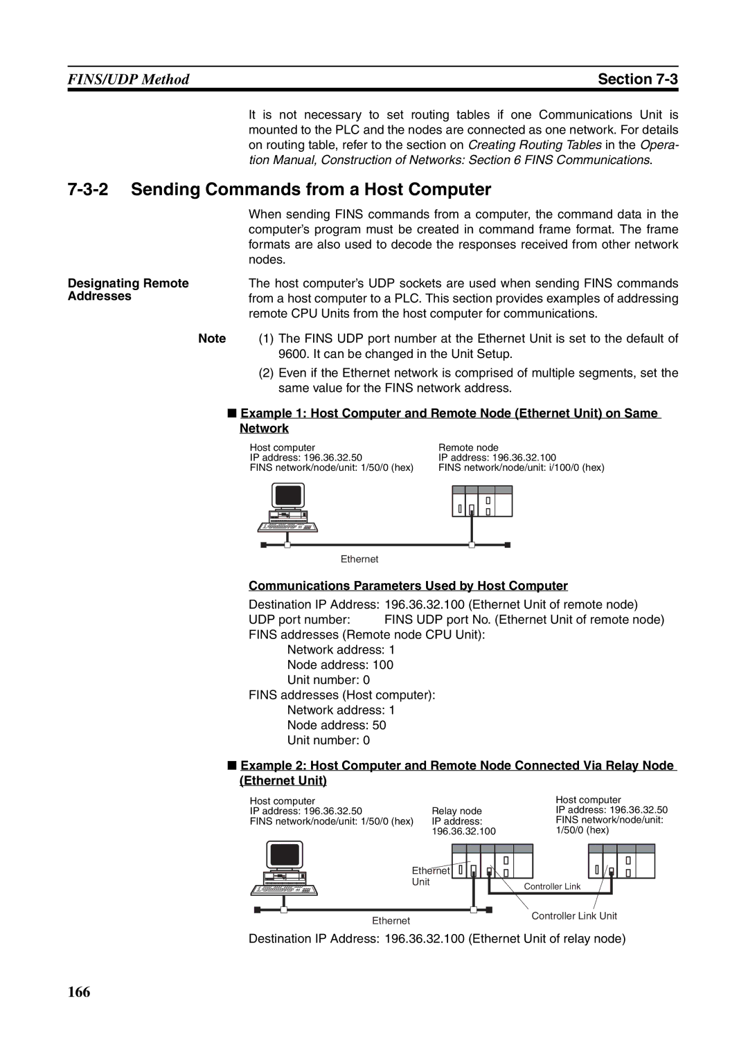
■Example 1: Host Computer and Remote Node (Ethernet Unit) on Same Network
Host computer | Remote node | ||||||||||||||||||||||||||||||
IP address: 196.36.32.50 | IP address: 196.36.32.100 | ||||||||||||||||||||||||||||||
FINS network/node/unit: 1/50/0 (hex) | FINS network/node/unit: i/100/0 (hex) | ||||||||||||||||||||||||||||||
|
|
|
|
|
|
|
|
|
|
|
|
|
|
|
|
|
|
|
|
|
|
|
|
|
|
|
|
|
|
|
|
|
|
|
|
|
|
|
|
|
|
|
|
|
|
|
|
|
|
|
|
|
|
|
|
|
|
|
|
|
|
|
|
|
|
|
|
|
|
|
|
|
|
|
|
|
|
|
|
|
|
|
|
|
|
|
|
|
|
|
|
|
|
|
|
|
|
|
|
|
|
|
|
|
|
|
|
|
|
|
|
|
|
|
|
|
|
|
|
|
|
|
|
|
|
|
|
|
|
|
|
|
|
|
|
|
|
|
|
|
|
|
|
|
|
|
|
|
|
|
|
|
|
|
|
|
|
|
|
Ethernet
Communications Parameters Used by Host Computer
Destination IP Address: 196.36.32.100 (Ethernet Unit of remote node)
UDP port number: FINS UDP port No. (Ethernet Unit of remote node) FINS addresses (Remote node CPU Unit):
Network address: 1
Node address: 100
Unit number: 0
FINS addresses (Host computer):
Network address: 1
Node address: 50
Unit number: 0
■Example 2: Host Computer and Remote Node Connected Via Relay Node (Ethernet Unit)
Host computer |
|
| Host computer | ||
IP address: 196.36.32.50 | Relay node | IP address: 196.36.32.50 | |||
FINS network/node/unit: 1/50/0 (hex) | IP address: | FINS network/node/unit: | |||
| 196.36.32.100 | 1/50/0 (hex) | |||
|
|
|
|
|
|
|
|
|
|
|
|
Ethernet
Unit
Ethernet
Controller Link
Controller Link Unit
Destination IP Address: 196.36.32.100 (Ethernet Unit of relay node)
166