Mail Send Function Status | Section |
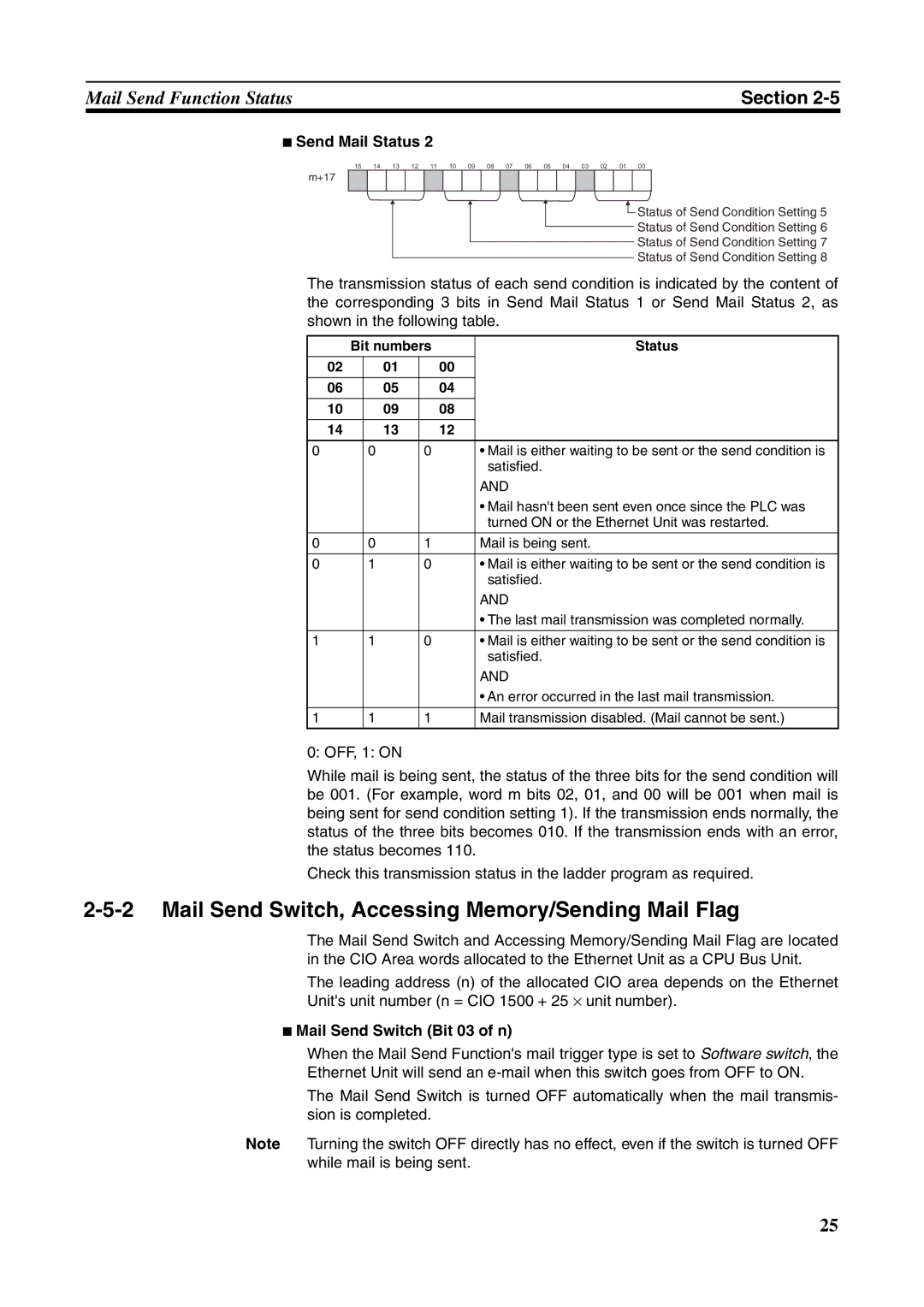
■Send Mail Status 2
15 | 14 | 13 | 12 | 11 | 10 | 09 | 08 | 07 | 06 | 05 | 04 | 03 | 02 | 01 | 00 |
m+17
![]() Status of Send Condition Setting 5
Status of Send Condition Setting 5
Status of Send Condition Setting 6
Status of Send Condition Setting 7
Status of Send Condition Setting 8
The transmission status of each send condition is indicated by the content of the corresponding 3 bits in Send Mail Status 1 or Send Mail Status 2, as shown in the following table.
| Bit numbers |
| Status | |||
|
|
|
|
|
|
|
02 |
|
| 01 |
| 00 |
|
|
|
|
|
|
|
|
06 |
|
| 05 |
| 04 |
|
|
|
|
|
|
|
|
10 |
|
| 09 |
| 08 |
|
|
|
|
|
|
|
|
14 |
|
| 13 |
| 12 |
|
|
|
|
|
|
|
|
0 |
| 0 |
| 0 |
| • Mail is either waiting to be sent or the send condition is |
|
|
|
|
|
| satisfied. |
|
|
|
|
|
| AND |
|
|
|
|
|
| • Mail hasn't been sent even once since the PLC was |
|
|
|
|
|
| turned ON or the Ethernet Unit was restarted. |
|
|
|
|
|
|
|
0 |
| 0 |
| 1 |
| Mail is being sent. |
|
|
|
|
|
|
|
0 |
| 1 |
| 0 |
| • Mail is either waiting to be sent or the send condition is |
|
|
|
|
|
| satisfied. |
|
|
|
|
|
| AND |
|
|
|
|
|
| • The last mail transmission was completed normally. |
|
|
|
|
|
|
|
1 |
| 1 |
| 0 |
| • Mail is either waiting to be sent or the send condition is |
|
|
|
|
|
| satisfied. |
|
|
|
|
|
| AND |
|
|
|
|
|
| • An error occurred in the last mail transmission. |
|
|
|
|
|
|
|
1 |
| 1 |
| 1 |
| Mail transmission disabled. (Mail cannot be sent.) |
|
|
|
|
|
|
|
0: OFF, 1: ON
While mail is being sent, the status of the three bits for the send condition will be 001. (For example, word m bits 02, 01, and 00 will be 001 when mail is being sent for send condition setting 1). If the transmission ends normally, the status of the three bits becomes 010. If the transmission ends with an error, the status becomes 110.
Check this transmission status in the ladder program as required.
2-5-2 Mail Send Switch, Accessing Memory/Sending Mail Flag
The Mail Send Switch and Accessing Memory/Sending Mail Flag are located in the CIO Area words allocated to the Ethernet Unit as a CPU Bus Unit.
The leading address (n) of the allocated CIO area depends on the Ethernet
Unit's unit number (n = CIO 1500 + 25 ⋅ unit number).
■Mail Send Switch (Bit 03 of n)
When the Mail Send Function's mail trigger type is set to Software switch, the
Ethernet Unit will send an
The Mail Send Switch is turned OFF automatically when the mail transmis- sion is completed.
Note Turning the switch OFF directly has no effect, even if the switch is turned OFF while mail is being sent.
25