TX-SA705 specifications
The Onkyo TX-SA705 is a versatile AV receiver designed for audiophiles seeking an immersive home theater experience. Combining advanced technology with user-friendly features, this receiver is well-suited for both casual listeners and serious home theater enthusiasts.One of the standout characteristics of the TX-SA705 is its impressive power output. Delivering 100 watts per channel across seven channels, it ensures that audio plays back with clarity and authority, providing enough power to fill large rooms with rich sound. The receiver supports a range of surround sound formats, including Dolby Atmos and DTS:X, allowing users to experience cinema-quality audio at home. These technologies create a three-dimensional sound environment, immersing listeners in the action.
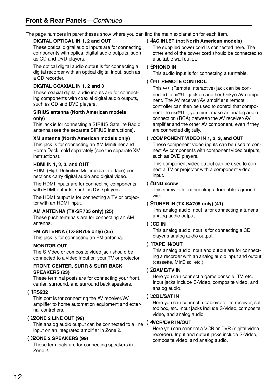
Connectivity is another key feature of the TX-SA705. The receiver is equipped with multiple HDMI inputs, supporting 4K video passthrough and HDR for stunning visuals. With ARC (Audio Return Channel) capability, the TX-SA705 simplifies the connection to compatible televisions, allowing for easy audio output. The inclusion of Bluetooth technology enables wireless streaming from smartphones and tablets, making it more convenient to enjoy music from various sources.
The Onkyo TX-SA705 also boasts an intuitive user interface designed for ease of use. The graphical user interface helps users navigate settings and options seamlessly, while the included remote control features direct access buttons for the most commonly used functions. Furthermore, the receiver is compatible with Onkyo's Controller app, providing additional control through smartphones.
In terms of sound customization, the TX-SA705 stands out with its advanced equalization features. The receiver incorporates Audyssey technology, which automatically calibrates audio settings based on room acoustics. This ensures optimal sound performance tailored to the specific environment.
Finally, the build quality of the TX-SA705 is noteworthy. Onkyo has designed this receiver with a sturdy chassis and high-quality components that enhance durability and performance. The TX-SA705 not only delivers impressive audio-visual performance but is also built to last, making it a wise investment for any home theater setup.
In summary, the Onkyo TX-SA705 combines powerful audio performance, modern connectivity options, and intelligent sound optimization features to create a receiver that meets the demands of contemporary home theater systems. Whether for movie nights or music playback, the TX-SA705 is a fantastic choice for an immersive entertainment experience.
