3.9 Connection of DECT Portable Stations
Notes
•The no. 4 and no. 5 pins (Master) of the CS must be connected to a pair of pins on the DHLC/DLC card. Then use 4 consecutive pairs of pins on the DHLC/DLC card, starting with the pins corresponding to the Master, as in the example above.
•When connecting multiple
•CS connections must be made within the same DHLC/DLC card.
•When a wrong connection is made, satisfactory performance of the CS cannot be guaranteed. Check the connection of CS and the PBX using the
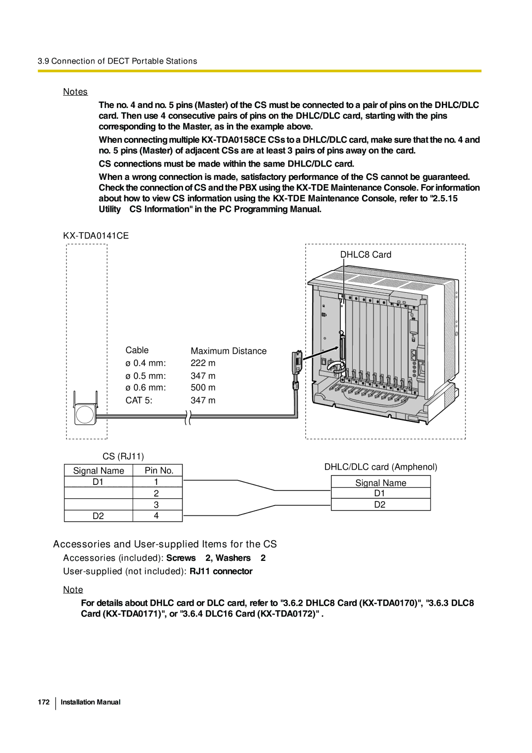
KX-TDA0141CE
DHLC8 Card
Cable
ø 0.4 mm: ø 0.5 mm: ø 0.6 mm: CAT 5:
CS (RJ11)
Signal Name | Pin No. |
D1 | 1 |
| 2 |
| 3 |
D2 | 4 |
Maximum Distance 222 m
347 m
500 m
347 m
DHLC/DLC card (Amphenol)
Signal Name
D1
D2
Accessories and User-supplied Items for the CS
Accessories (included): Screws × 2, Washers × 2
User-supplied (not included): RJ11 connector
Note
For details about DHLC card or DLC card, refer to "3.6.2 DHLC8 Card