4.2 PC Connection
IMPORTANT
To protect the system, keep the following in mind:
1.Make sure that both connector cases (frame ground) of the
2.If this is not possible, connect the frame of the PBX to the frame of the PC using an earthing wire in order to prevent difference in the electrical potentials.
Note
For pin assignments and maximum cabling distance, refer to "3.12.1 Connection of Peripherals".
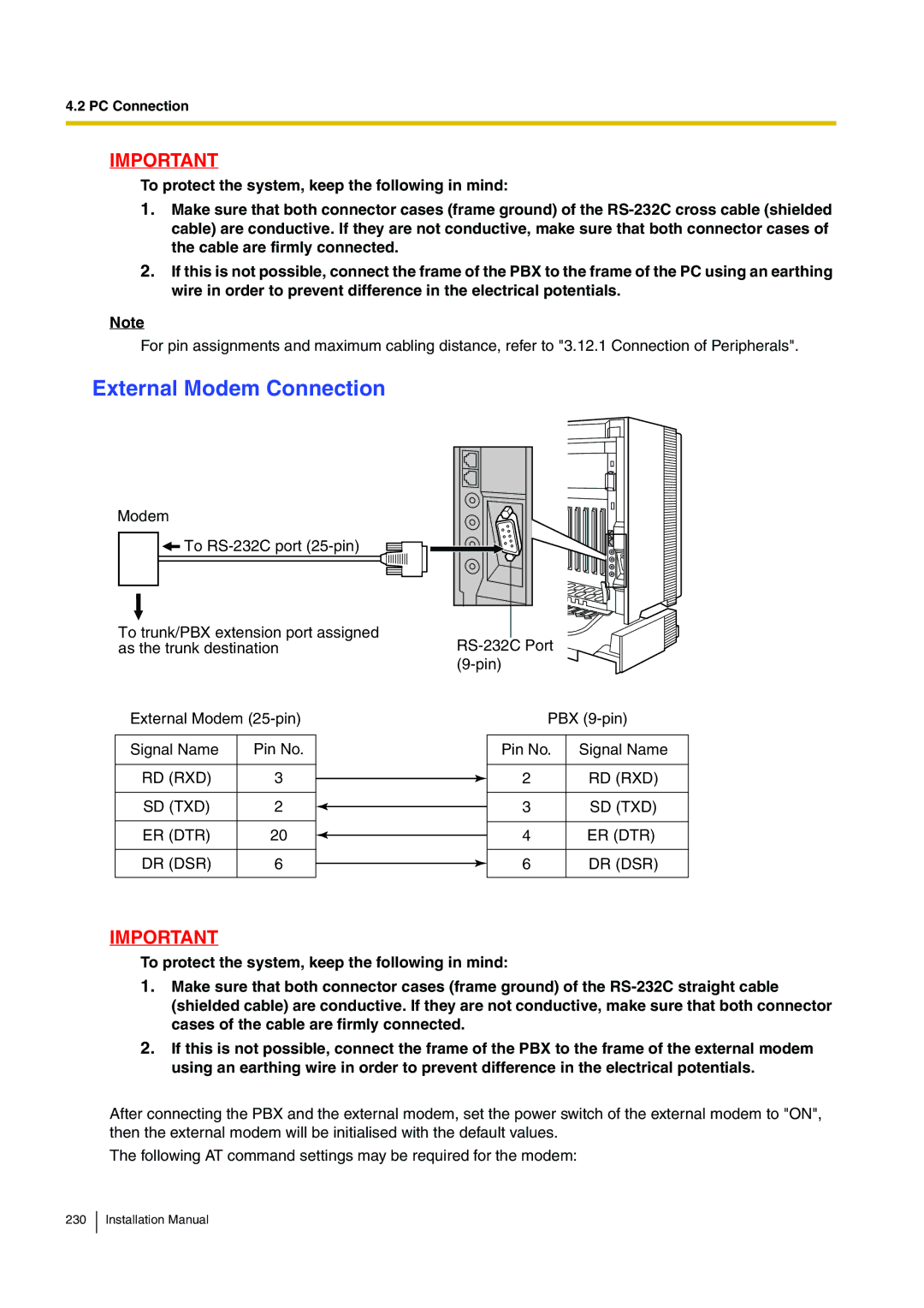
External Modem Connection
Modem
![]() To
To
To trunk/PBX extension port assigned as the trunk destination
External Modem
Signal Name | Pin No. |
|
|
RD (RXD) | 3 |
|
|
SD (TXD) | 2 |
|
|
ER (DTR) | 20 |
|
|
DR (DSR) | 6 |
|
|
PBX
Pin No. Signal Name
2 | RD (RXD) |
3SD (TXD)
4ER (DTR)
6 | DR (DSR) |
IMPORTANT
To protect the system, keep the following in mind:
1.Make sure that both connector cases (frame ground) of the
2.If this is not possible, connect the frame of the PBX to the frame of the external modem using an earthing wire in order to prevent difference in the electrical potentials.
After connecting the PBX and the external modem, set the power switch of the external modem to "ON", then the external modem will be initialised with the default values.
The following AT command settings may be required for the modem: