PT-DW10000E
Models No. PT-D10000E
Serial number
Dear Panasonic Customer
Model number PT-D10000E/PT-DW10000E
Contents
Important Safety Notice
Fuse
Important the Moulded Plug U.K. only
Getting Started
Precautions with regard to safety
Do not handle the power cord plug with wet hands
Insert the power cord plug securely into the wall outlet
Do not overload the wall outlet
Insulate the battery using tape or similar before disposal
Do not place the projector into water or let it become wet
Do not disassemble the lamp unit
Do not place liquid containers on top of the projector
Use only the specified battery
Always disconnect all cables before moving the projector
Do not place any heavy objects on top of the projector
Do not look into the lens while the projector is being used
Getting Started
Before Using
Accessories
Maintenance
Disposal
To view clear images
Screen
Front
Remote control unit
Location and function of each part
Side Top Bottom
Lamp LAMP1, LAMP2, LAMP3, LAMP4
Projector Main Unit
Rear
Power Standby
Side Controls
Connection terminals
Loading batteries
Using the remote control unit
Effective range of remote control operation
Setting projector ID number to remote control
Using a wired remote control
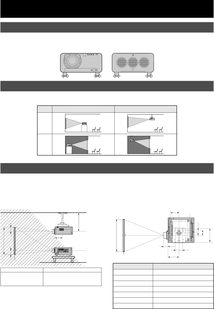
Installation
Examples of system expansion
Projection scheme
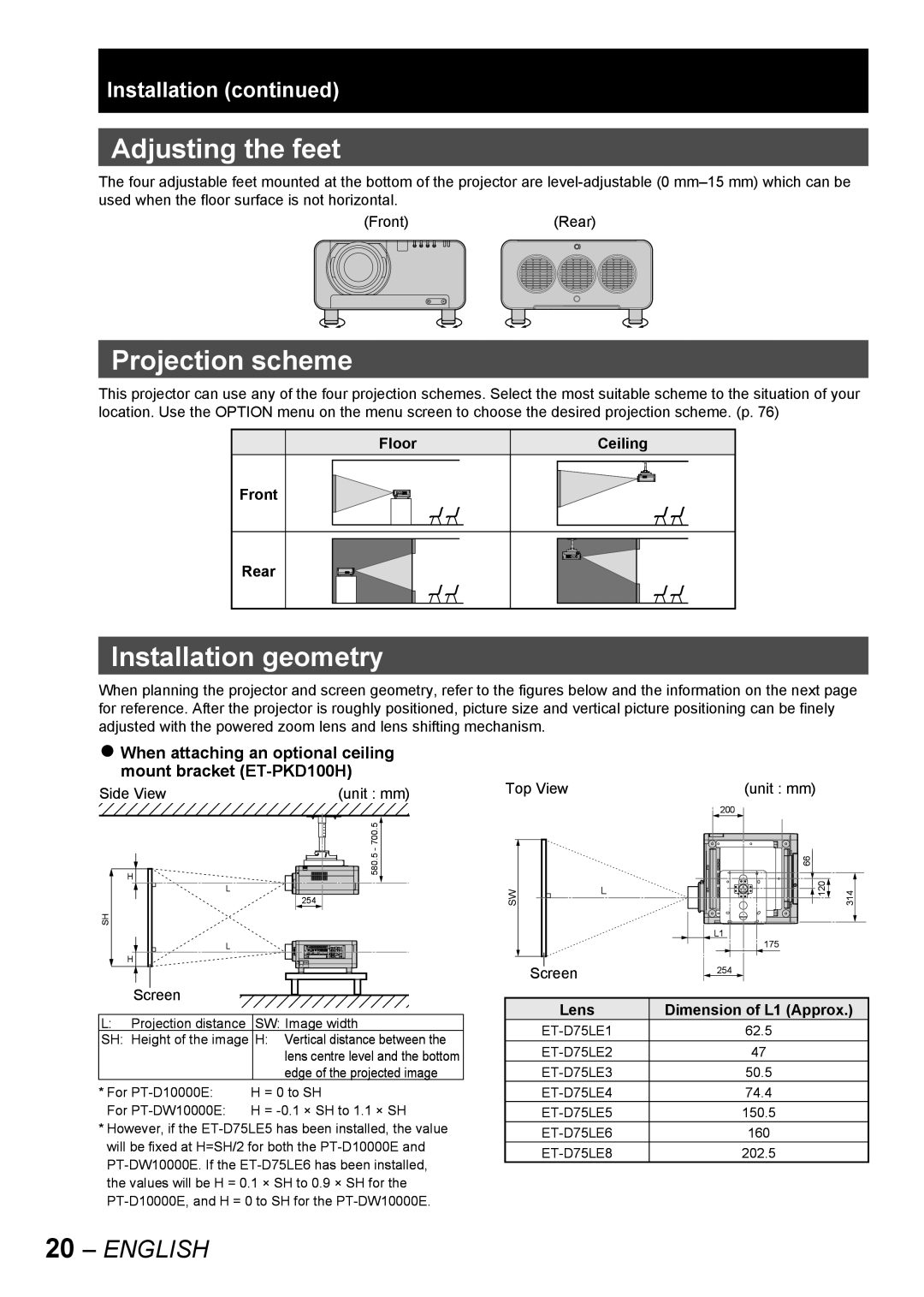
Adjusting the feet
Installation geometry
Side View Top View
Started
Getting
Installation
Calculation formulas for projection distance by lens types
Pin Signal
Connection
Before starting connection
Pin No
Example of connecting with Video devices
Control PC Video deck TBC built-in
Control PC
Example of connecting with personal computers
Control PC To 2nd projector Serial in terminal
Installation of input module optional
Installing the input module
Module Module model Terminal Signal formats supported
Types of the input modules optional
Procedure of installation
Fix the input module Register the input signal
Remove the slot cover
Insert the input module
Connecting signals to the input module
Signal Projector
Business digital
High-vision DVI-D input module
Connecting the signal to the SD-SDI input module
SD-SDI input module optional
ET-MD77SD1 for 480i/576i
LAN terminal*1
Connecting the signal to the HD/SD-SDI input module
HD/SD-SDI input module optional
ET-MD77SD3 for HD/SD
LAN terminal *1
Connecting signals to the DVI-D input module
DVI-D input module optional
How to install the projection lens
How to remove the projection lens
Projection lens cover lock button
Projection lens lock button
Power indicator lamp
Connecting the power cord
Installation
Indicator Projector status Status
Powering up the projector
Making adjustment and selection
Press Power on
# $
Powering off the projector
# Press Power Standby
Press the marked side
Confirmation screen will appear
How to adjust the lens
How to adjust the focus, zoom and shift
Model number PT-D10000E PT-DW10000E Projection lens
Adjustment range after lens position optical shift
Moving the projection lens position to the home position
Automatic adjustment Auto Setup
Registration of input signal data
Registration of new data
Press Enter
Press to display
Clearing the data of registered signals
Sub memory
Basic
Enter
Restrictions
Press to select the SUB
Press on normal screen
Switching the input signal
Basic Operation Using the Shutter function
On-screen display function
Status function
Automatic adjustment
Using the FUNC1 button
Turning on button illumination
Displaying the internal test pattern
Changing the picture aspect ratio
Press Aspect on the remote control
Setting will change as follows each time Aspect is pressed
On-screen menus
Main Menu item
Test Pattern p Signal List pp Network pp
Position pp
Advanced Menu pp
Display Language p
Using the menu screens
Resetting to the factory default
Adjusting the picture
Switching the picture mode
Press to switch Picture
Press to select Picture
Adjusting Colour
Adjusting Contrast
Adjusting Brightness
Temp
Adjusting Tint
Adjusting the colour temperature
Sharpness
Sharpness setting
Gamma setting
Noise reduction setting
Dynamic iris setting
Reduction
Iris
Setting the system format
Selector
RGB1/RGB2/DVI-D terminal input signals
SRGB is only enable when RGB signals are being input
Display the Picture screen. p Press to select Picture
Press to select Natural Press to select Color
Adjusting the position
Shift adjustment
Adjustment
Press to select Shift
Adjusting the aspect ratio
Press to switch Aspect
Operation
Press to select Aspect
Adjusting the zoom ratio
Clock phase adjustment
Phase
Interlocked
Press to adjust
Keystonedistortion correction
Keystone
Keystone screen will be displayed
How to use Advanced Menu
Press to switch Digital
Digital cinema reality
Press to select Digital
Blanking adjustment
Press to select Input Resolution
Press to select Blanking
Press to select Total
Blending
Adjusting the clamp position
Edge blending adjustment
Adjust
Frame delay
Press to select Frame Delay
Press to switch Frame
Delay
Press to adjust the position PT-D10000E
Raster position
Press to select Raster Position
PT-DW10000E
Setting the Display Language
Changing the display language
Press to select the desired language
Display Language
Option1 settings
Adjusting colour matching
Basic Operation Special Features
Press to switch Color Matching
Adjusting the colour
Matching using a colorimeter
Press to switch Large
Large Screen Correction
Data
Press to select R, G, B or Cy, Mg, Ye, Wh Press Enter
Auto signal
Automatic adjustment Only RGB input
Signal
Setup
Back Colour
Color
Press to switch AUX DVI
Press to switch P in P
Press to select AUX DVI
Edid
Press to select FUNC1
Setting FUNC1
Press to switch FUNC1
Position of on-screen indications
OSD memory
Position
Memory
Option2 settings
Setting a projector ID
Projector ID
Press Menu twice
Installation Setting
Installation
Altitude
Press to select Altitude
Resolution
Direction
Press to select Output
Horizontal
Press to switch Lamp
Lamp select
Press to select Lamp
Select
Relay
RS-232C setting
Lamp relay
Information
System information Cleaning the air filter
Cleaning
Setting the date and time
Press to select Date
Time
Clock
Setting the startup logo
Password
Press to switch Startup
Press to select Startup
Displaying the internal test pattern
Test pattern
Cycle of displayed internal test patterns
Pattern
How to use network function
Initial setting of network function
Hold down Default for 3 seconds
Press to select Store
Network connections
Name and function of network function parts
LAN terminal 10BASE-T/100BASE-TX
LAN LINK/ACT lamp green
Click Change password
Accessing from the Web browser
Press OK and the top page will appear Password change
Basic control
Lens adjustment Test pattern display
Detail control
Monitor information
Menu display
Error information
When Failed has appeared for an item
Mail setup
English
DNS server set up
Button to update settingsFeatures
Special
Numbers 0 9, period
Authentication server setting
Ping test
Contents of mail sent
Adjust clock
Network config
Firmware update
Using the PJLink protocol
Supported commands
PJLink security authorization
Command Control details
Setting the security
Setting the password
Password
Displaying the security screen
Setting the text
Changing the password
Password Change
Press to set the password
Changing the text
Press to select Text
Change
Text screen will be displayed
Examples of connection
Using the serial terminals
Communication conditions Factory setting
Pin assignments and signal names
Pin Signal Description No. name
For RS-422
Sub 9-pin male
Control commands
Command Function of command Remarks
Basic format
Accepted
1st 2nd RS-422 OUT
Cable specifications
Projector Computer DTE Specifications
Using the Remote 2 terminal
Example of a control panel layout
Pin assignments and control
Names of terminals Open H Short L
Lamp 3 monitor Lamp
Indication of monitor lamp
Lamp 1 monitor Lamp
Cleaning and replacement of air filter
Procedure of cleaning
Place the filter cleaning unit
Use a vacuum cleaner to remove any dust blockages
Install the brush cover so that it
Replacement of lamp unit
Precautions on lamp unit replacement
Timing of lamp unit replacement
Indication after 1 800 hours
Procedure of lamp unit replacement
Lamp unit cover
Eye bolt
Installation procedure
Eye bolt Wire
Symptoms Check point
Power does not turn on
Remote control does not
No image appears on screen
Self-diagnosis display
Self Details Remedy Diagnosis Display
FE1
Specifications
Model No PT-D10000E PT-DW10000E
RGB2 input
Compatible RGB/YPBPR/DVI-D Signals
Appendix
List of P in P
Main window
Installation dimensions diagram
Dimensions
Outside dimensions
Adjusting colour matching
Index
Trademark Acknowledgement
For business users in the European Union