Model No Outdoor Units
Indoor Units
…In Moist or Uneven Locations
For safe installation and trouble-free operation, you must
…In a Room
…In an Area with High Winds
Check of Density Limit
Precautions for Installation Using New Refrigerant
Configuration and characteristics of cylinders
Contents
Tentative
Specifications Unit Specifications Way Cassette Type
Model No
Indoor Unit 36PU1U6 Outdoor Unit 36PE1U6
Indoor Unit 42PU1U6 Outdoor Unit 42PE1U6
Indoor Unit 26PU1U6 Outdoor Unit
Indoor Unit 36PU1U6 Outdoor Unit 36PS1U6
Indoor Unit 42PU1U6 Outdoor Unit 42PS1U6
Specifications Unit Specifications Wall Mounted Type
Data Subject to Change Without Notice
Indoor Unit 26PK1U6 Outdoor Unit
Specifications Unit Specifications Ceiling Type
Performance
Indoor Unit 36PT1U6 Outdoor Unit
Indoor Unit 42PT1U6 Outdoor Unit
Indoor Unit 26PT1U6 Outdoor Unit 26PS1U6
17˚F BTU / h Moisture removal High Pints / h
Indoor Unit 42PT1U6 Outdoor Unit 42PS1U6
Specifications Unit Specifications Low Silhouette Duct Type
Net weight Lbs. kg 128 Shipping weight 148 Shipping volume
Indoor Unit 36PF1U6 Outdoor Unit 36PE1U6
RCZ-RTC2
CZ-RWSC1U
Major Component Specifications Indoor Unit
Fan motor
Model No 36PU1U6 Source
Model No 42PU1U6 Source
Model No 26PK1U6 Source
Model No 26PT1U6 Source
Model No 36PT1U6 Source
Model No 42PT1U6 Source
Model No 26PF1U6 Source
Model No 36PF1U6 Source
Specifications Major Component Specifications Outdoor Unit
Compressor
CR-CH4872R Microprocessor
Lbs. kg R410A 7.9
26PS1U6
230V, 40µF
42PS1U6
Specifications Other Component Specifications Outdoor Unit
Model No 26PE1U6, U-26PS1U6
Model No 36PE1U6, U-36PS1U6
Model No 42PE1U6, U-42PS1U6
Ø1/8
Hol
Page
19/32
31/32 12-7/32
Dimension inch
56-25/32 Air outlet duct flange
Thickness more than T1/16 inch
Page
Page
Specifications
Temperature Indoor Air Intake Outdoor Air Intake
Operating Range
Page
Specifications Noise Criterion Curves Way Cassette Type
Source
Specifications Noise Criterion Curves Wall Mounted Type
Specifications Noise Criterion Curves Ceiling Type
Noise Criterion Curves Low Silhouette Duct Type
Sound
Specifications Noise Criterion Curves Outdoor Units
Indoor Fan Performance Type
Specifications Increasing the Fan Speed
How to read the diagram
Type
Model 36, 42 Type
Air throw distance chart Way Cassette Type
Model 26 Type
Specifications Air throw distance chart Wall Mounted Type
Model 42 Type
Air throw distance chart Ceiling Type
Model 36 Type
Outdoor Unit Type Time delay fuse or Circuit capacity
Wiring System Diagrams
How to Connect Wiring to the Terminal For stranded wiring
Installation Instructions
Ashrae
Selecting the Installation Site
Air-Discharge Chamber for Top Discharge
For U-42PES1U6 unit
① Air discharge chamber ② Air discharge chamber base
42PES1U6 unit
Direction
Front and both sides must remain open
25-13/32 25/32
30-5/64 Wind direction
Obstacle to the front of unit
Installation in front-rear rows
Drainage Work
Installing the Outdoor Unit
Routing the Tubing and Wiring
Low Silhouette Ducted Type Way Cassette Type
Way Cassette Type U1 Type Suspending the Indoor Unit
Preparation for Suspending
Placing the Unit Inside the Ceiling
Installing the Drain Piping
Checking the Drainage
Before Installing the Ceiling Panel
Unit body
Installing the Ceiling Panel
When Removing the Ceiling Panel for Servicing
Accessories
Installing the ceiling panel
Located
Trical wiring or conduits are
Selecting and Making a Hole
Hole Dia. inch
If Block, Brick, Concrete or Similar Type Wall
Installing the Rear Panel on the Wall
If Wooden Wall
How to replace the grille
Removing the Grille to Install the Indoor Unit
How to remove the grille
To mount the indoor unit on the rear panel
Wiring Instructions General Precautions on Wiring
How to remove the cover plate
Installing the Drain Hose
Shaping the Tubing
Ceiling Type T1 Type Suspending the Indoor Unit
Hinge Slide toward front side Side panel Unit
Outside
Duct for Fresh Air
Good Not good
26PF1U6
Required Minimum Space for Installation and Service
Low Silhouette Ducted Type F1 Type
36PF1U6
Extreme care in supporting
Enough to support the weight
It is important that you use
Indoor unit inside the ceiling
Tighten the hose clamps so
Their locking nuts face upward
Indoor control board
When you short the pin on
Be careful since the fan will start
To mount the tube cover, use 5/16
Increasing the Fan Speed
Indoor Fan Performance
When Installing the Indoor Unit
Checkpoint after installation
Checkpoint Symptom Remark
If Wall-mounted Fixed Position
Wireless Remote Controller Installation
How to Install Batteries
Setting the Model Code
Room Temperature Sensor Setting
Address Switches
CZ-RWSU1U
Ceiling Type T1 Type Indicator Section Installation
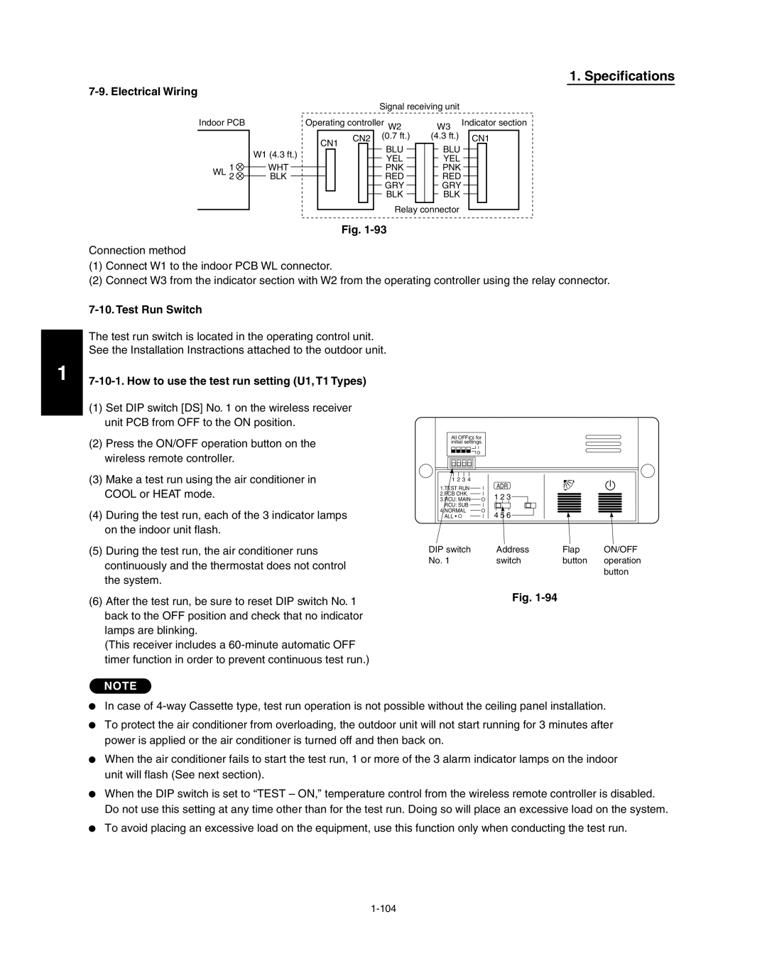
How to use the test run setting U1, T1 Types
Electrical Wiring
Test Run Switch
Cause of Trouble
Misoperation Alarm Indicators
Alarm
Lamp
If Wall mounted Fixed Position
107
Equipment, use this
To avoid placing an
Excessive load on
Function only when
Timer Standby
Bright Cause of Trouble
Wiring procedure
Will damage the equipment
Wiring System Diagram for Group Control
Group control using 2 signal receiving units
Setting method
Check Items Before the Test Run
Test Run Procedure Wall mounted Type K1 Type
Wireless remote controller transmitter
Controller
Test run Using the controller For S-26PK1U6
Indicator
Precautions
Test OFF
Nos , 2, 3 all OFF
26PK1U6
Nos , 2 OFF, No on
Indoor unit
Diagnosis Table
Cause
HOW to Install the Timer Wired Remote Controller
Tube diameter Tightening torque Tube thickness
Insulating the Refrigerant Tubing Tubing Insulation
Precautions for Packed Valve Operation
Never grasp the drain or refrigerant connecting
Tubes arranged together
Finishing the Installation
Taping the Tubes
Leak Test
Air Purging with a Vacuum Pump for Test Run Preparation
Manifold gauge Vacuum pump
Designed for use with R410A
Evacuation
Use a cylinder specifically
R410A
Charging Additional Refrigerant
Finishing the Job
Processes and Functions
Cooling
Processes and functions Room Temperature Control
Chart Summary and Explanations
Processes and functions Heating
Cold Draft Prevention Heating Cycle
Chart Explanations and notes
Automatic Fan Speed Indoor Unit
Outdoor unit fan control
Discharge temperature release control
Current release control
Coil heating control
Current release value shift control
Freeze prevention low-temperature release control
Overcurrent protection control
Heating high-load control
Defrost control
Outdoor Unit Control PCB
Outdoor Unit Control PCB CR-CH4272R
Method of System Address Setting
Example of wiring
Page
Electrical Data
Indoor Units
Page
Electrical data Wall Mounted Type S-26PK1U6
Electrical data Wall Mounted Type S-26PK1U6
Electrical data Ceiling Type S-26PT1U6, S-36PT1U6, S-42PT1U6
Electrical data Ceiling Type S-26PT1U6, S-36PT1U6, S-42PT1U6
Page
Page
Outdoor Units
Outdoor Units
26PS1U6
Outdoor Units
36PE1U6
Outdoor Units
36PS1U6
Outdoor Units
42PE1U6
Outdoor Units
42PS1U6
Outdoor Units
Page
Service Procedures
Service procedures Meaning of Alarm Messages
Contents of remote controller switch alarm display
Wireless
Remarks
Remote Alarm Judgment condition Clear condition
Contents Correction
Alarm
Eeprom
MDC trouble
Service procedures Details of Alarm Messages
Alarm P29
Alarm P26
HIC PCB trouble
26, 36 Type
Alarm E31
HIC-CH4872R HIC-CH2672R
Communications Trouble within unit
Alarm P22
Alarms F04, F06, F07, F08, F12
Sensor installation Sensor type Location
Check procedure
Sensor Temperature Correlation Table
Exchanger Temp. C1 Sensor, Heat Exchanger Temp. C2 Sensor
Check Pin
Outdoor Air Temp. TO, Intake Temp. TS, Heat
Discharge Temp. TD Sensors
Outdoor Unit Maintenance Remote Control
Outdoor unit maintenance remote control Overview
All units test run Operation
Switching between cooling/heating Operation
All units start/stop Operation
Item code Display contents
Sample displays
Display for unit Nos
Item code Meaning of Code
Display of first 3 digits Display of last 3 digits
List of Item Codes
Item code Parameter
Outdoor unit maintenance remote control
Figures represent the capacity data for each model
Test RUN
Preparing for Test Run
Test run
Test run U1, K1, T1, F1 Type 6-2. Caution
Items to Check Before the Test Run
Cause
Test run Examples of Wiring Diagrams
Basic wiring diagram
Remote controller crossover wiring for group control
2P DIP switch Rotary switch
Setting the outdoor unit system addresses
Automatic address setting using the remote controller
System address No
Remote controller setting mode
Main-sub remote controller control
Connecting 2 remote controllers to control 1 indoor unit
201201