B – Command Line Interface Show Command
Q
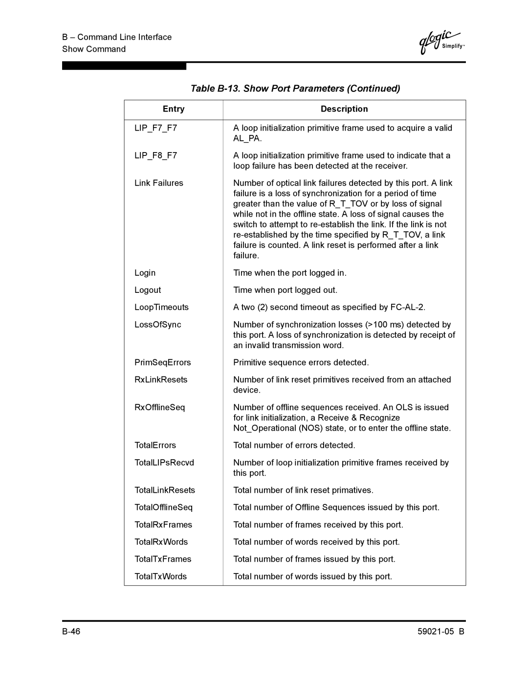
Table | |
|
|
Entry | Description |
|
|
LIP_F7_F7 | A loop initialization primitive frame used to acquire a valid |
| AL_PA. |
LIP_F8_F7 | A loop initialization primitive frame used to indicate that a |
| loop failure has been detected at the receiver. |
Link Failures | Number of optical link failures detected by this port. A link |
| failure is a loss of synchronization for a period of time |
| greater than the value of R_T_TOV or by loss of signal |
| while not in the offline state. A loss of signal causes the |
| switch to attempt to |
| |
| failure is counted. A link reset is performed after a link |
| failure. |
Login | Time when the port logged in. |
Logout | Time when port logged out. |
LoopTimeouts | A two (2) second timeout as specified by |
LossOfSync | Number of synchronization losses (>100 ms) detected by |
| this port. A loss of synchronization is detected by receipt of |
| an invalid transmission word. |
PrimSeqErrors | Primitive sequence errors detected. |
RxLinkResets | Number of link reset primitives received from an attached |
| device. |
RxOfflineSeq | Number of offline sequences received. An OLS is issued |
| for link initialization, a Receive & Recognize |
| Not_Operational (NOS) state, or to enter the offline state. |
TotalErrors | Total number of errors detected. |
TotalLIPsRecvd | Number of loop initialization primitive frames received by |
| this port. |
TotalLinkResets | Total number of link reset primatives. |
TotalOfflineSeq | Total number of Offline Sequences issued by this port. |
TotalRxFrames | Total number of frames received by this port. |
TotalRxWords | Total number of words received by this port. |
TotalTxFrames | Total number of frames issued by this port. |
TotalTxWords | Total number of words issued by this port. |
|
|