MB200i Printer
Sato America, Inc
Table of Contents
Adjustment Procedures
Introduction
About this Manual
General Description
Theory of Operation
Switches and Indicators
Switches
Technical Data
Physical Characteristics
Power
Environmental
Processing
Character Font Capabilities
Character Control
BAR Code Capabilties
Interface Specifications
Interface Specifications AD-HOC Connectivity
Interface Specifications
802.11B Wireless Interface
802.11B Wireless Specifications
RS232C Specifications
RS232C Serial Interface
READY/BUSY Cable Requirements DB9
Host Direction PIN Printer
Irda Specifications BHT Protocol
Irda Specifications Standard Protocol
Infrared Rays Irda
Irda Specifications Ircomm Protocol
Irda Specifications IrOBEX Protocol
Bluetooth
Receive Buffer
ALL Interface Types
ACK/NAK Protocol
Printer Setup
AD-HOC Connectivity
3a/b, Sato MB200i Properties
Sato MB200i Configuration Tool
Computer Setup
Network Connections
Advanced
10, Wireless Network Properties
12a/b, Ports
14, TCP/IP Wizard Welcome Screen
16, TCP/IP Wizard Exit Screen
17, Sato MB200i Properties
Display Fields LCD Screens Maintenance Mode
LCD Display
Display Fields
Battery Level
Icon Description
Wireless Field Strength
Operational Status
Normal Mode Status
Test Print Mode Status LCD Detail
LCD Screens
Startup Status LCD Detail
Factory Clear Mode Status LCD Detail
Default Setting Mode Status LCD Detail
HEX Dump Mode Status LCD Detail
Printer Errors Status LCD Detail
Maintenance Mode Status LCD Detail
Maintenance Mode
LCD Setup Status Detail
Wireless LAN Status LCD Detail
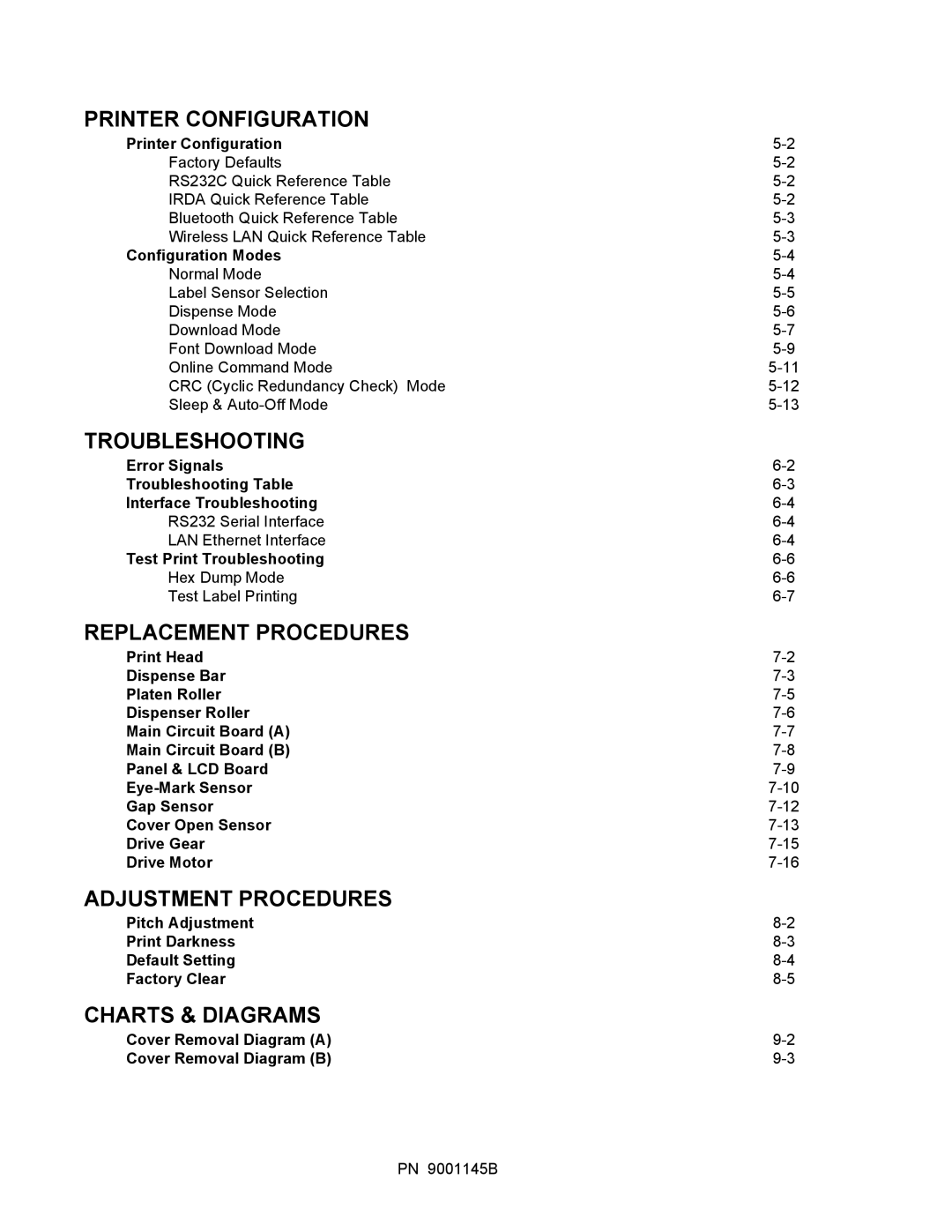
Printer Configuration
Printer Configuration Configuration Modes
Printer Configuration
Factory Defaults DSW1 DSW2 DSW3 DSW4
RS232C Quick Reference Table Description DIP Switches Head
Irda Quick Reference Table Description DIP Switches Head
User Test Print Mode Opened
Configuration Modes
Normal Mode
Power = OFF
Label Sensor Selection
Auto
Dispense Mode
Manual
Download Mode
Orange and enters
Unit 5 Printer Configuration
Font Download Mode
Format storage area if Never done
Status Description Acsii
HEX Transfer
Online Command Mode
Online Command Mode
CRC Cyclic Redundancy Check Mode
CRC Check Mode
Sleep & AUTO-OFF Mode
Sleep & Auto-Off Mode
Unit 5 Printer Configuration PN 9001145B
Troubleshooting
Error Signals
LED Mode Description
Image Voids
Light Print Images
Uneven Print Darkness
Smeared Print Images
Interface Troubleshooting
CHK Troubleshooting Step
Test Print Troubleshooting
HEX Dump Mode
Test Print Mode
Test Label Printing
Replacement Procedures
Replacement Procedures
Print Head Replacement
Dispense BAR Replacement
1b, Print Head Replacement
2b, Despense Bar Replacement
Platen Roller Replacement
3a, Platen Roller Replacement
Dispense Roller Replacement
Dispenser Roller
Main Circuit Board a Replacement
Main Circuit Board a Replacement
Main Circuit Board B Replacement
Main Circuit Board B Replacement
Panel & LCD Board Replacement
Panel & LCD Board Replacement
EYE-MARK Sensor Replacement
8a, Eye-Mark Sensor Replacement
8c, Eye-Mark Sensor Replacement
GAP Sensor Replacement
9a, Gap Sensor Replacement
COVER-OPEN Sensor Replacement
9b, Gap Sensor Replacement
10b, Cover-Open Sensor Replacement
Drive Gear Replacement
11, Gear Replacement
Drive Motor Replacement
12, Drive Motor Replacement
Adjustment Procedures
Adjustment Procedures
Pitch Adjustment
Print Darkness
Print Darkness
Default Setting Mode
Print + Power
Factory Clear Mode
Factory Clear Mode
Unit 8 Adjustment Procedures PN 9001145B
Charts & Diagrams
Cover Removal Diagram
Cover Removal Diagram
1a, Cover Removal Diagram
1b, Housing Cover Removal
Unit 9 Charts & Diagrams PN 9001145B
