Unit 7: Replacement Procedures
GAP SENSOR REPLACEMENT
1Switch off the printer and remove power supply.
2Remove the front housing cover.
NOTE: Figure
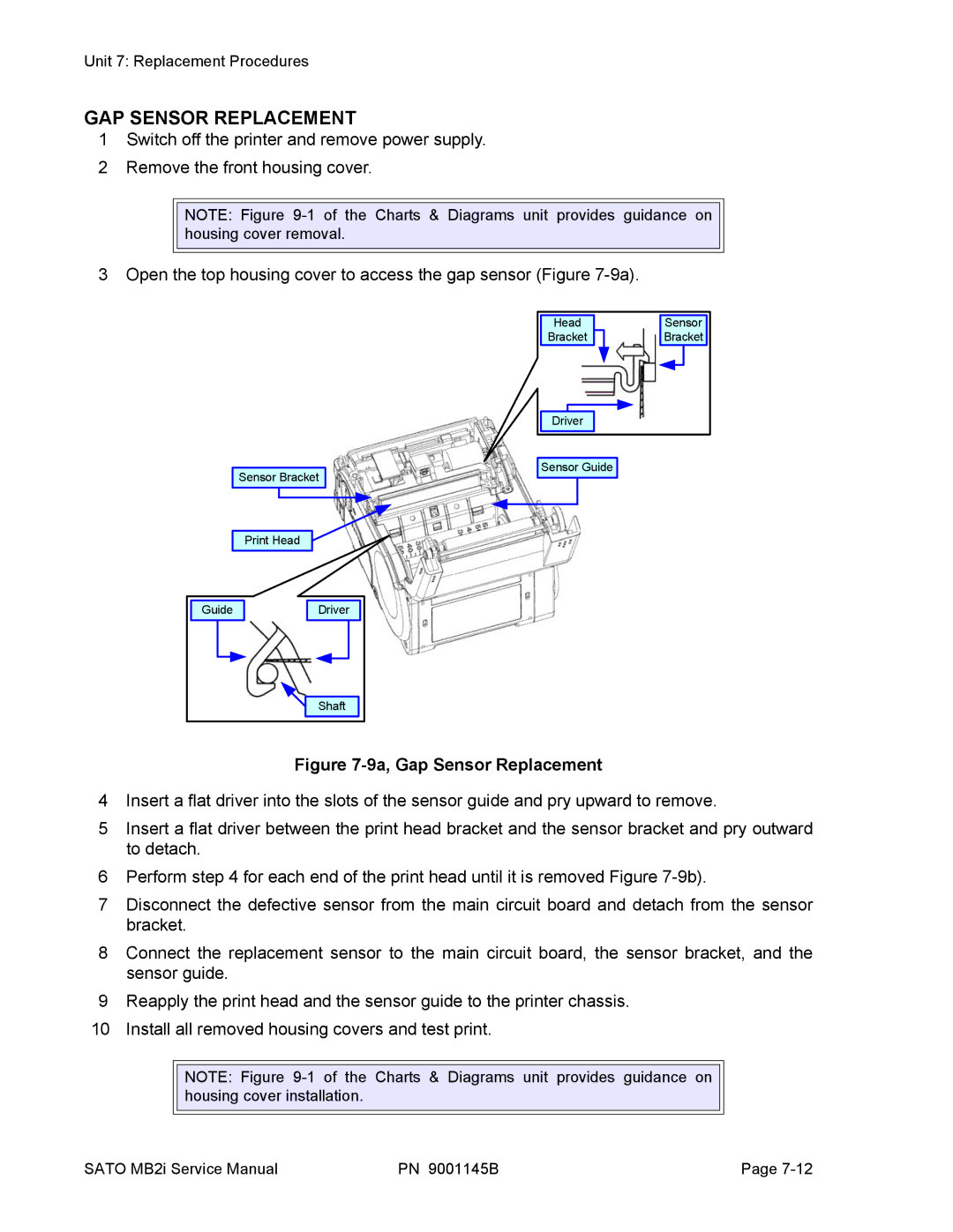
3 Open the top housing cover to access the gap sensor (Figure
Sensor Bracket
Head |
Bracket |
Driver |
Sensor Guide
Sensor |
Bracket |
Print Head
Guide |
Driver |
Shaft |
Figure 7-9a, Gap Sensor Replacement
4Insert a flat driver into the slots of the sensor guide and pry upward to remove.
5Insert a flat driver between the print head bracket and the sensor bracket and pry outward to detach.
6Perform step 4 for each end of the print head until it is removed Figure
7Disconnect the defective sensor from the main circuit board and detach from the sensor bracket.
8Connect the replacement sensor to the main circuit board, the sensor bracket, and the sensor guide.
9Reapply the print head and the sensor guide to the printer chassis.
10 Install all removed housing covers and test print.
NOTE: Figure
SATO MB2i Service Manual | PN 9001145B | Page |