Unit 7: Replacement Procedures
MAIN CIRCUIT BOARD (B) REPLACEMENT
1Perform steps 1 through 4 of the Main Circuit Board (A) Replacement procedure.
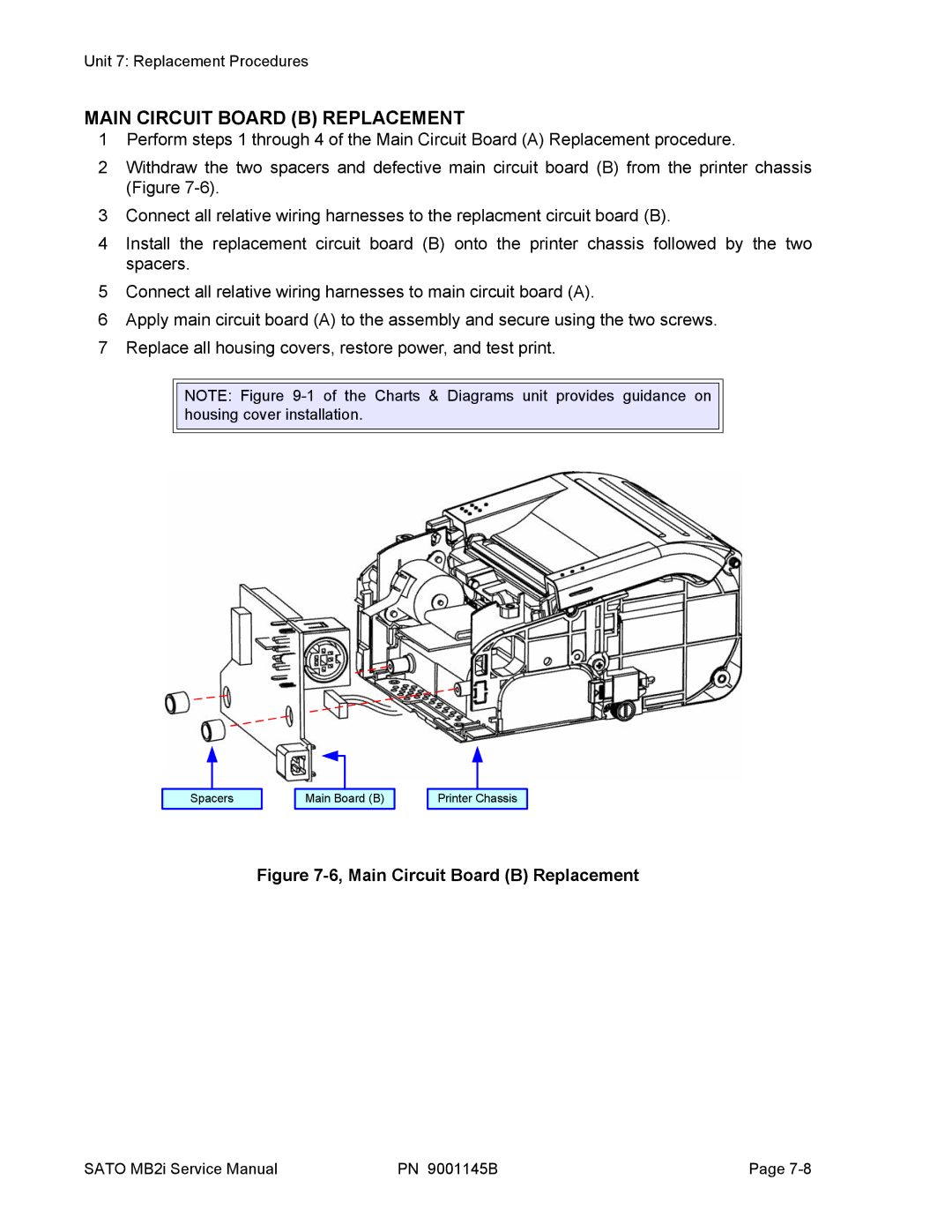
2Withdraw the two spacers and defective main circuit board (B) from the printer chassis (Figure
3Connect all relative wiring harnesses to the replacment circuit board (B).
4Install the replacement circuit board (B) onto the printer chassis followed by the two spacers.
5Connect all relative wiring harnesses to main circuit board (A).
6Apply main circuit board (A) to the assembly and secure using the two screws.
7Replace all housing covers, restore power, and test print.
NOTE: Figure
Spacers
Main Board (B)
Printer Chassis
Figure 7-6, Main Circuit Board (B) Replacement
SATO MB2i Service Manual | PN 9001145B | Page |