Unit 7: Replacement Procedures
MAIN CIRCUIT BOARD (A) REPLACEMENT
1Switch off the printer and remove power supply.
2Remove the front, top, left, and right housing covers.
NOTE: Figure
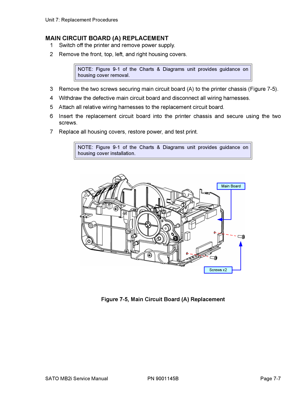
3Remove the two screws securing main circuit board (A) to the printer chassis (Figure
4Withdraw the defective main circuit board and disconnect all wiring harnesses.
5Attach all relative wiring harnesses to the replacement circuit board.
6Insert the replacement circuit board into the printer chassis and secure using the two screws.
7Replace all housing covers, restore power, and test print.
NOTE: Figure
Main Board
Screws x2
Figure 7-5, Main Circuit Board (A) Replacement
SATO MB2i Service Manual | PN 9001145B | Page |