SECTION 1 - GENERAL INFORMATION
|
| |||
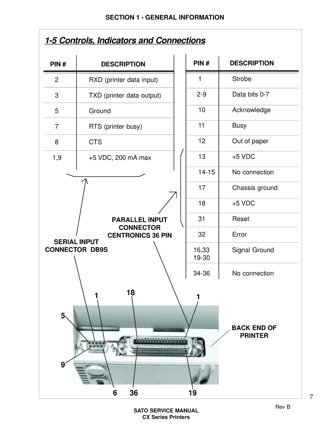
PIN # | DESCRIPTION | PIN # | DESCRIPTION | |
2 | RXD (printer data input) | 1 | Strobe | |
3 | TXD (printer data output) | Data bits | ||
5 | Ground |
| 10 | Acknowledge |
7 | RTS (printer busy) | 11 | Busy | |
8 | CTS |
| 12 | Out of paper |
1,9 | +5 VDC, 200 mA max | 13 | +5 VDC | |
|
|
| No connection | |
|
|
| 17 | Chassis ground |
|
|
| 18 | +5 VDC |
| PARALLEL INPUT | 31 | Reset | |
|
| CONNECTOR | 32 | Error |
| CENTRONICS 36 PIN | |||
SERIAL INPUT |
|
|
| |
CONNECTOR DB9S |
| 16,33 | Signal Ground | |
|
|
|
| |
|
|
| No connection | |
| 1 | 18 | 1 |
|
|
|
| ||
5 |
|
|
|
|
|
|
|
| BACK END OF |
|
|
|
| PRINTER |
9 |
|
|
|
|
| 6 | 36 | 19 | 7 |
|
|
|
| |
SATO SERVICE MANUAL
CX Series Printers
Rev B
