Quantum Hot Standby
USE 106
Page
Table of Contents
Planning a Quantum Hot Standby System
Using a Quantum 984 Hsby System
Theory of IEC Hsby Operation
Using a Quantum IEC Hot Standby System
Additional Guidelines for IEC Hot Standby
Ethernet Hot Standby Solution
Maintenance
Appendix C ProWORX Nxt Configuration
Specifications for CHS 110 Hot Standby
Appendix a Com Act Error Patterns
Appendix B Fiber Optic Cable Guide
Page
Important Information
Safety Information
Procedure
Please Note
Persons Schneider Electric All Rights Reserved
Validity Note
About the Book
At a Glance
Related Documents
About the Book
What’s in this
Overview of Quantum Hot Standby
Purpose
Chapter?
Overview of Quantum Hot Standby
Purpose What’s in this Section?
1Control
Introduction
Role of the CHS
Primary and Standby Control
Description
Hot Standby
Hardware Components in a Quantum Hot Standby System
Cables See Fiber Optic Cable Guide, p
Panel Controls
CHS 110 Hot Standby Module
Topology
Module
Following table shows the five status indicators
LED Display
140 CHS 110
Update Button
Keyswitch
Slide Switch
Function
Hsby Modes of Hsby has three Modes of Operation
2Operation
Modes of Operation
Operation
Primary unit fails
Run Mode
Ignores your action
3Cabling
Connections
Fiber Optic Cable
Cable
CHS 210 Hot Standby Kit
Hsby and IEC Hsby
Quantum 984 Hot Standby involves
Hsby
Architecture
Module Version
IEC compliant languages FBD, LD, SFC, IL and ST
Upgrade PLC firmware
RIO is serviced differently
Hsby system
Fiber Optic CHS Link 5HPRWRUJUDWHU
Standby
Overview
Theory of 984 Ladder Logic Hsby Operation
This chapter contains the following topics
How a 984 Hsby System Works
Solve Segment Scan
System Scan Time
Primary Rack Scan
Transfer Rate
Scan Time Increase table below
PLC to CHS Data
Leads to the following results
Example
Scan Time Increase Table in PLC Scan Times, p
State RAM Transfer and Scan Time
Time
Theory of 984 Hsby Operation
Transfer Primary to the Standby controller on every scan
Default Transfer Area
Automatic
Example
Custom State
Alternatives to the default transfer area
Customizing Options
Area
Custom Scans
Setting up
Up using multiple scans to transfer all the data
Custom Scans
Theory of 984 Hsby Operation
Theory of IEC Hsby Operation
Following are IEC Hot Standby definitions
IEC Hot Standby Definitions
Definitions
IEC runtime system
Program Data
IEC Heap
Currently used IEC Heap Size and the Maximum IEC Heap Size
Online -- Memory Statistics
Program. There are three steps in the transfer process
How an IEC Hsby System Works
IEC Theory
State RAM Defined
System Scan Time
Standby Rack
Transfer diagram The following shows a transfer diagram
Primary Rack
IEC Scan Time Increase
Time Scan Time Increase Table below
Following result
IEC Scan Time Increase Table See Overall PLC Scan Time, p
State Ram Transfer and Scan Time
Configured for IEC Hsby
Standby’s IEC data consistency
Layout
Transferred RAM
Theory of IEC Hsby Operation
Planning a Quantum Hot Standby System
Controllers
Guidelines for Planning a Hot Standby System
Primary
Positioning
Electrical Safety Precautions
Safety Precautions
Remote I/O Cable Topologies
Single Cable
Single Cable Configuration
Configuration
Standby PLC
Dual Cable Configuration
Dual Cable Standby system
Primary PLC
Procedure
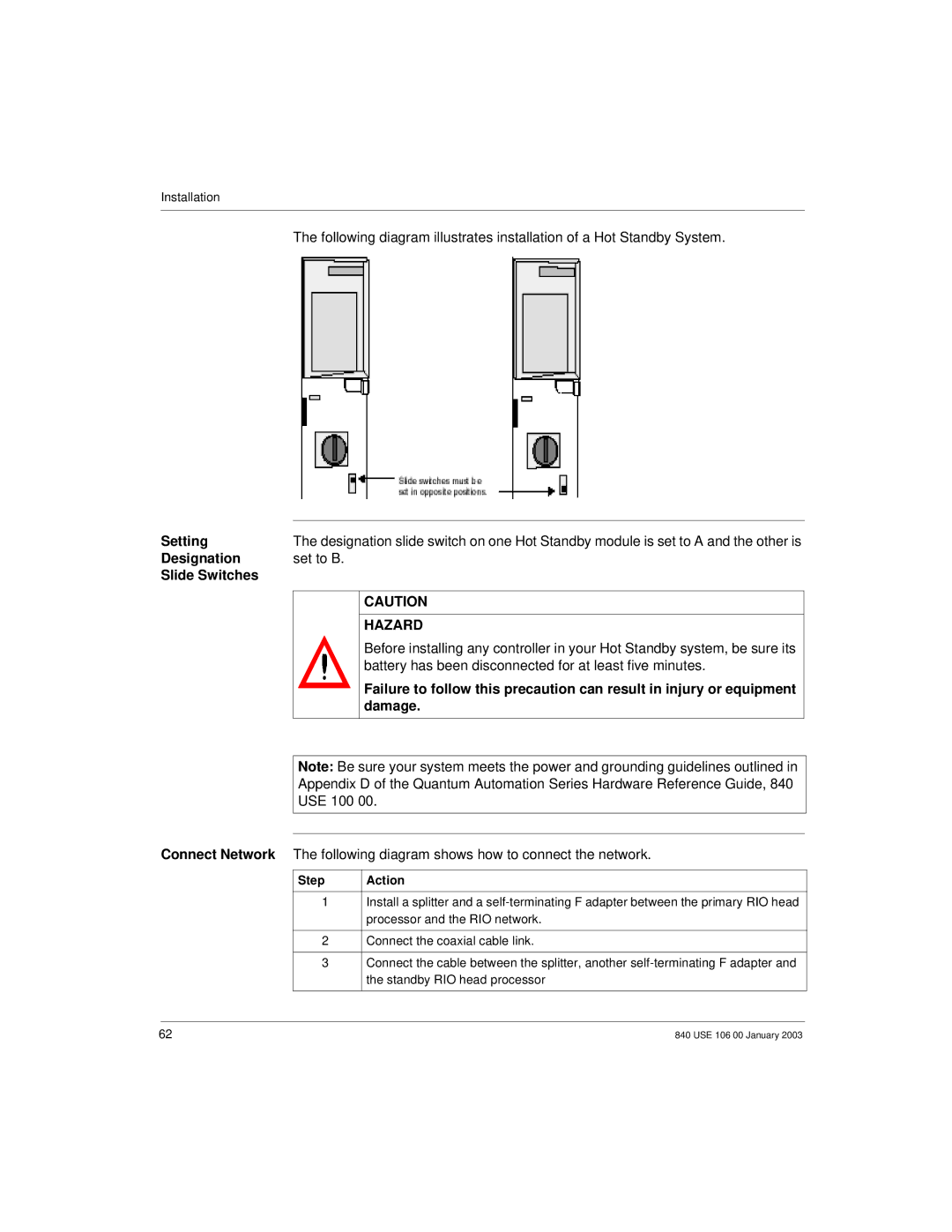
Installation
How to Install a Hot Standby System
Installing a Hot
Battery has been disconnected for at least five minutes
Setting
Designation Set to B Slide Switches
Damage
Following diagram illustrates the network connections
Network
Step
Diagram
Aligning Key Locking Ring
Adding Hot
Converting to You need backplanes with at least four slots
Using a Quantum 984 Hsby System
Using a Quantum 984 Hsby System
1Configuration
Modsoft
Configuring 984 Hsby
CHS
System by CHS
Installed into your application
Controlling
Instruction
Extension
Configuration Extension
Hot Standby System by
System
Hsby System Active
Execute Hsby Unconditionally Enable Command
CHS Instruction
Using the CHS Instruction Block
Using CHS Instruction Block
Hot Standby Command Register Hazard
Command Register
Nontransfer Area Within the State RAM Transfer
Elements of the Nontransfer Area
Status Register
Configuration
CHS module
Screens must be identical to those in the CHS block
Zoom screen of CHS Instruction
Zoom Screen
Bits in the Hot
Hot Standby Status Register
Status Register
Standby Status Register
Reverse Transfer Registers
Transfer Logic
Reverse Transfer Logic Example
Reverse
Segment 000813
Using Configuration Extension
Using a Quantum 984 Hsby System
Concept shown
Hot Standby Dialog
Dialog Standby Concept
Bits in the Hot Standby Command Register
Commandsystem Register
Hot Standby Command Register Hazard
Run
Keyswitch Override and Run Mode
Keyswitch Override Hazard
Override
Option
Power up the system again. Download the new configuration
Software Control Example
Standby on Logic Mismatches
Mismatch Hazard
Port Address
Switchover
Modbus Plus
Swapping at
Transferred if this check box is activated
Transfer All State RAM
Transfer All
Check box Nontransfer Area
Hot Standby Status Register for Configuration Extension
Status Register for Configuration extension
Advanced Options
Advanced
Defining the Transfer Area of State RAM
Additional RAM State RAM dialog
Dialog
12K Option
User Defined Option State RAM Transfer
Transferring Additional State RAM Data
Transfer Additional State RAM Hazard
101
Begins again, sending the first 512 additional registers
Scan Transfers
Data Type
4Operation
Step Action
Starting Your Hot Standby System
Preconditions Starting the System
Standby Backplane
Ready Fault
RIO Head
Synchronization
Synchronizing Time-of-Day Clocks
Clock
Network 2 of Segment
Following diagram shows synchronizing time-of-day clocks
Network 1 of Segment
While Your System Is Running
Using a Quantum IEC Hot Standby System
This chapter presents operating procedures for the IEC Hsby
Using a Quantum IEC Hot Standby System
This section describes Quantum IEC Hot Standby configuration
Loading the Software
@2IE V196
Concept Loadables Installation Screen
@1SE V196 @2I7
V208
IEC Logic in a
Standby controller executes the logic of segment
Transfer from Primary to Standby
Using
Extensions
Loadables are removed from the project automatically
Hot Standby Dialog
Concept 2.5 shown
Activation of Hot
Standby Dialog
Specify
Specifying the Command Register
Standby Command Register
Register is
Range
Hot Standby Command Register
Enable it
Register. However
Control Example
Enable Keyswitch Override
Software
Software Control
Options for
Option
Stage Description Comment
Exec Upgrade Without Stopping Application Stopped Cancel
Advanced Options Concept
System Executive Upgrade Procedure
Stopping the process
Logic Mismatch
Map / Configuration Hazard
Standby on Logic Mismatch
For Concept
Logic
Updating Project
Data that do not exist on both controllers is not updated
Project global data that is updated includes
Global Data
Swapping Addresses at Switchover
Is also
Matter if they reside in the Standby or Primary rack
IP Address
NOE 771 cannot be controlled, it is always activated
Standby Backplanes
Using a Quantum IEC Hot Standby System
State RAM
Nontransfer Area of State RAM
4nnnnn
Controllers
Supported only with Concept 2.5 or higher
Registers
Diagram below shows a PLC Memory Partition
Memory Partition
Shows how the number of IEC Hsby Registers can be modified
State RAM Size
State RAM Size
Section Transfer Control
Section Transfer Control
FBD
Select Component of Type Bool
Starting
5Operation
Preconditions
Regardless of its designation as a or B
140
CHS 110 RIO Head
Normal Operation
Map
Memory/Scantime optimization
IEC State RAM
142
Screenshot of the Memory Prediction dialog is shown below
Memory Prediction
For IEC Hot Standby data
Memory
Statistics
Synchronizing Time of Day Clocks
Regular Data
Constant Internal
Monitoring
Transfers
Additional Guidelines for IEC Hot Standby
Additional Guidelines for IEC Hot Standby
General Application Requirements
Existing IEC
Memory Savings
Assessing
Applications
Memory Statistics
Memory Following screen shows memory statistics Statistics
152
Optimization
IEC Applications
Needed to achieve it
RAM Registers
Configured State
Efficient Use of State RAM
Anything else
Efficient Use
IEC Application
Data
Efficiency Tips
RealF RealG RealH
Use Constants Instead of Equal Literals
RealB RealC RealD
Use Constants Instead of Open Inputs
160
Programmed Logic
Reduce the Use Of Complex Data Structures
Ethernet Hot Standby Solution
Solution
Please Note
Overview of Hot Standby Solution for NOEs
Solution
Service NOE 771
Hot Standby Topology
Drop
To download a project to the PLC
NOE Configuration and Hot Standby
Device can be assigned the configured IP + 1 address
Transparency
Configuring
IP Address Assignment
Standalone Mode
Primary Mode
Secondary Mode
Offline Mode CPU is stopped
Address
Effects on IP Address assignment and Ethernet services
Offline Mode at Power-up Sequence table
Assignment
Effects on the Ethernet services
Power-Up
Services
Ethernet
Going to Offline
Additional
Information
IP Address Assignment and Going Offline
Connections
Service Typical Swap Time Maximum Swap Time
Address Swap Times
Remote Connection Request during Hot Standby Swap
Network Effects of Hot Standby Solution
Browsers
Hot Standby Swap during Remote Connection Request
Publish
Service
Scanning
Subscribe
176
Maintenance
Maintenance
Health of a Hot Standby System
Verifying Health of a Hot Standby System
Health Messages
Additional Checks
Recognizing
Avoid Damage to Application I/O Devices
Safety
Or equipment damage
Errors
Startup Errors
Interface Errors
Communications Errors
Troubleshooting
LEDs
Replace the faulty CHS 110 module
Board Level Errors
Board Level Error 140 CHS 110
10.3 Failures
Components
Detecting Failures in a Hot Standby System
Main
Backplane
Controller CHS RIO Head Failure Type Description
Standby module and RIO head to the chart below
Detecting Failures in the Primary Backplane
Detecting Failures in the Standby Backplane
Controller CHS RIO Head Failure Description
191
Replacement
Primary Backplane Hazard
Replacement
Replacing a Hot Standby Module
Updating
Changing the Program and Performing a Program Update
Battery Hazard
Standby Ogic
Before You
Program Change Hazard
Standby controller Off Line
Begin Controller as well
Updating Standby Procedure
Amber Standby indicator begins to blink Updating Standby
Updating PLC System Executives in a 984 Hsby System
Standby is Running
Steps to Upgrade Zoom or RDE PLC executives
While Hot
Updating PLC System Executives in an IEC Hsby System
Switchover Forcing a Manually
Testing
Forcing a Switchover
Take the following steps to force a switchover manually
Primary Standby
After Taking the Primary Controller Offline
Bringing the Original Primary Unit Back Online
Through
Register, p
Specifications for CHS 110 Hot Standby
Specifications for CHS 110 Hot Standby
Specifications
Specifications for CHS 110 Hot Standby
Included here
Appendices
At a Glance
Appendix contains the following chapters
Appendices
Com Act Error Patterns
Purpose What’s in this Chapter?
Number Blinks Code Error
CHS 110 Hot Standby Module Error Patterns
CHS 110 Error
Patterns
Number Code Error Blinks
CRP Remote I/O Head Processor Error Patterns
Error Patterns The following table shows error patterns
212
Fiber Optic Cable Guide
Dations
Connectors
Recommen
Other Tools
Suggested Tools include
Other Tools
Menu and select Hsby Extension from the Tree Control
ProWORX Nxt Configuration
ProWORX Nxt Hot Standby Configuration Extension
Dialog Screen
Hot Standby Qua
Hot Standby Quantum dialog screen
Field
Functions
Parameters of a Quantum Hot Standby system
Status Register
Initial Command Register
Status Registers Dialog screen
Registers dialog screen
Offline state
Index Numerics
Index
Automatic, 108 swapping addresses
226