2. Hardware Implementation of the LUFP7 Gateway
2) Cables: |
|
VW3 A8 306 R•• Modbus cable | Shielded cable with a male RJ45 connector at each |
(“star” topology / “bus” topology with tap boxes) | end. |
VW3 A68 306 Modbus cable | Shielded cable with a male RJ45 connector and a |
(“bus” topology with tap boxes) | male 15 point |
| a Modbus subscriber (slave or master) to a |
| TSXSCA62 or TSXCA50 box. |
Shielded double twisted pair Modbus cable | Bare cable (without connectors) used to make up the |
(“bus” topology with branch boxes) | main section of the Modbus network. There are three |
| items available: TSXCSA100 (100 m), TSXCSA200 |
| (200 m), and TSXCSA500 (500 m). |
2.6. Connecting the LUFP7 gateway to the Profibus-DP Network
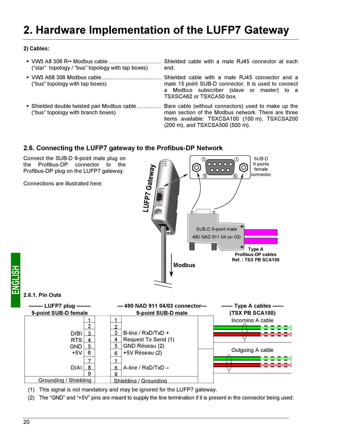
Connect the
Connections are illustrated here:
g | c | |
|
| 9 points |
|
| female |
k | h | connector |
490 NAD 911 04 (or 03) |
Type A |
Ref. : TSX PB SCA100 |
Modbus |
2.6.1. Pin Outs
–—— LUFP7 plug ——– 9-point SUB-D female
1
2
D(B) 3 RTS 4 GND 5 +5V 6
7 D(A) 8 9
Grounding / Shielding
—490 NAD 911 04/03 connector—
9-point SUB-D male
1
2
3
4Request To Send (1)
5GND Réseau (2)
6+5V Réseau (2)
7
8
Shielding / Grounding
—— Type A cables ——
(TSX PB SCA100)
Incoming A cable
Outgoing A cable
(1)This signal is not mandatory and may be ignored for the LUFP7 gateway.
(2)The “GND” and “+5V” pins are meant to supply the line termination if it is present in the connector being used.
20
