6. Configuring the Gateway
Then you should save and export the configuration of the
8)Configuring the inputs and outputs of the
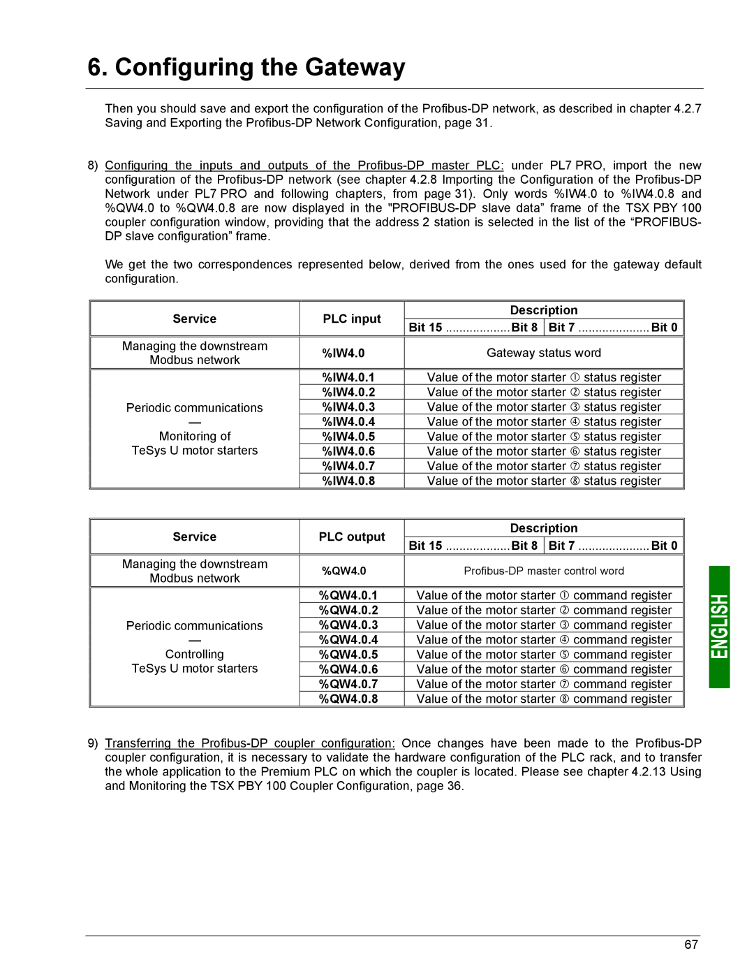
We get the two correspondences represented below, derived from the ones used for the gateway default configuration.
Service | PLC input | Description | ||
Bit 15 ...................Bit 8 | Bit 7 ..................... Bit 0 | |||
|
| |||
Managing the downstream | %IW4.0 | Gateway status word | ||
Modbus network | ||||
|
|
| ||
| %IW4.0.1 | Value of the motor starter c status register | ||
Periodic communications | %IW4.0.2 | Value of the motor starter d status register | ||
%IW4.0.3 | Value of the motor starter e status register | |||
— | %IW4.0.4 | Value of the motor starter f status register | ||
Monitoring of | %IW4.0.5 | Value of the motor starter g status register | ||
TeSys U motor starters | %IW4.0.6 | Value of the motor starter h status register | ||
| %IW4.0.7 | Value of the motor starter i status register | ||
| %IW4.0.8 | Value of the motor starter j status register | ||
|
|
| ||
Service | PLC output | Description | ||
Bit 15 ...................Bit 8 | Bit 7 ..................... Bit 0 | |||
|
| |||
Managing the downstream | %QW4.0 | |||
Modbus network | ||||
|
|
| ||
| %QW4.0.1 | Value of the motor starter c command register | ||
Periodic communications | %QW4.0.2 | Value of the motor starter d command register | ||
%QW4.0.3 | Value of the motor starter e command register | |||
— | %QW4.0.4 | Value of the motor starter f command register | ||
Controlling | %QW4.0.5 | Value of the motor starter g command register | ||
TeSys U motor starters | %QW4.0.6 | Value of the motor starter h command register | ||
| %QW4.0.7 | Value of the motor starter i command register | ||
| %QW4.0.8 | Value of the motor starter j command register | ||
9)Transferring the
67