11. Appendix D: Sample Use under PL7 PRO
11.3. Controlling and Supervising the 8 TeSys U Motor Starters
The “Supervision Control” operating screen (see picture below) is meant to monitor the status of the 8 TeSys U motor starters, numbered from 1 to 8. It is also meant to control them individually using several buttons.
Registers 455 and 704 of each of the 8 TeSys U motor starters are used to conduct this control and supervision:
455 – TeSys U status register (IEC61915)
Bit 0 | Motor starter ready | ||||
..........Bit 1 | Contactor in the ON position ( | 1 | ) | ||
..........Bit 2 | Fault (trip or dropout) |
|
| ||
Bit 3 | Alarm presence | ||||
..........Bit 4 | Specific: Tripped ( | I >> | ) | ||
..........Bit 5 | Specific: Fault reset | authorized | |||
Bit 6 | Specific: | ||||
Bit 7 | Specific: Motor running | ||||
Bits | |||||
Bit 14 | Reserved: Local control | ||||
Bit 15 | Ramping (motor starting) | ||||
704 – (IEC61915) command register
Bit 0 | Reserved: Run forward |
Bit 1 | Reserved: Run reverse |
Bit 2 | Reserved (stopping) |
Bit 3 | Reset |
Bit 4 | Reserved (emergency start) |
Bit 5 | Self test: Triggering test (trip) |
Bit 6 | Reserved (low speed) |
Bits | |
Bit 12 | Specific: Overload (shunt trip) |
Bit 13 | Specific: Pause (reserved for adjustment) |
Bits
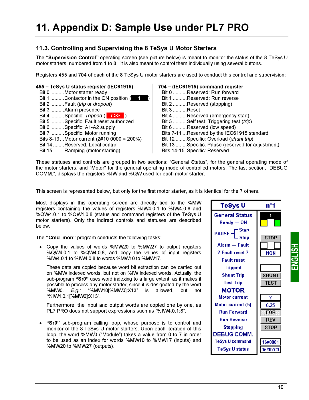
These statuses and controls are grouped in two sections: “General Status”, for the general operating mode of the motor starters, and "Motor" for the general operating mode of controlled motors. The last section, “DEBUG COMM.”, displays the registers %IW and %QW used for each motor starter.
This screen is represented below, but only for the first motor starter, as it is identical for the 7 others.
Most displays in this operating screen are directly tied to the %MW registers containing the values of registers %IW4.0.1 to %IW4.0.8 and %QW4.0.1 to %QW4.0.8 (status and command registers of the TeSys U motor starters). Only the indirect controls and statuses are described below.
The “Cmd_mon” program conducts the following tasks:
•Copy the values of words %MW20 to %MW27 to output registers %QW4.0.1 to %QW4.0.8, and copy the values of input registers %IW4.0.1 to %IW4.0.8 to words %MW10 to %MW17.
These data are copied because word bit extraction can be carried out on %MW indexed words, but not on %IW indexed words. Actually, the
Furthermore, the input and output words are copied one by one, as PL7 PRO does not support expressions such as “%IW4.0.1:8”.
•“Sr0”
101