6. Configuring the Gateway
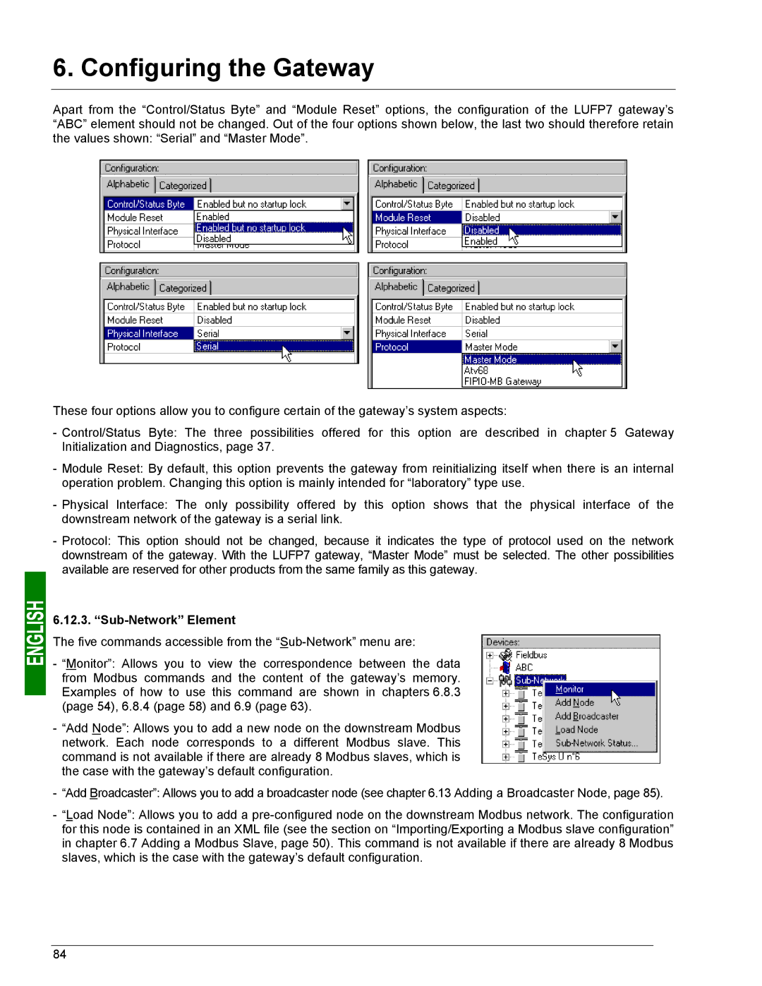
Apart from the “Control/Status Byte” and “Module Reset” options, the configuration of the LUFP7 gateway’s “ABC” element should not be changed. Out of the four options shown below, the last two should therefore retain the values shown: “Serial” and “Master Mode”.
These four options allow you to configure certain of the gateway’s system aspects:
-Control/Status Byte: The three possibilities offered for this option are described in chapter 5 Gateway Initialization and Diagnostics, page 37.
-Module Reset: By default, this option prevents the gateway from reinitializing itself when there is an internal operation problem. Changing this option is mainly intended for “laboratory” type use.
-Physical Interface: The only possibility offered by this option shows that the physical interface of the downstream network of the gateway is a serial link.
-Protocol: This option should not be changed, because it indicates the type of protocol used on the network downstream of the gateway. With the LUFP7 gateway, “Master Mode” must be selected. The other possibilities available are reserved for other products from the same family as this gateway.
6.12.3. “Sub-Network” Element
The five commands accessible from the
- “Monitor”: Allows you to view the correspondence between the data from Modbus commands and the content of the gateway’s memory. Examples of how to use this command are shown in chapters 6.8.3 (page 54), 6.8.4 (page 58) and 6.9 (page 63).
-“Add Node”: Allows you to add a new node on the downstream Modbus network. Each node corresponds to a different Modbus slave. This command is not available if there are already 8 Modbus slaves, which is the case with the gateway’s default configuration.
-“Add Broadcaster”: Allows you to add a broadcaster node (see chapter 6.13 Adding a Broadcaster Node, page 85).
-“Load Node”: Allows you to add a
84