6. Configuring the Gateway
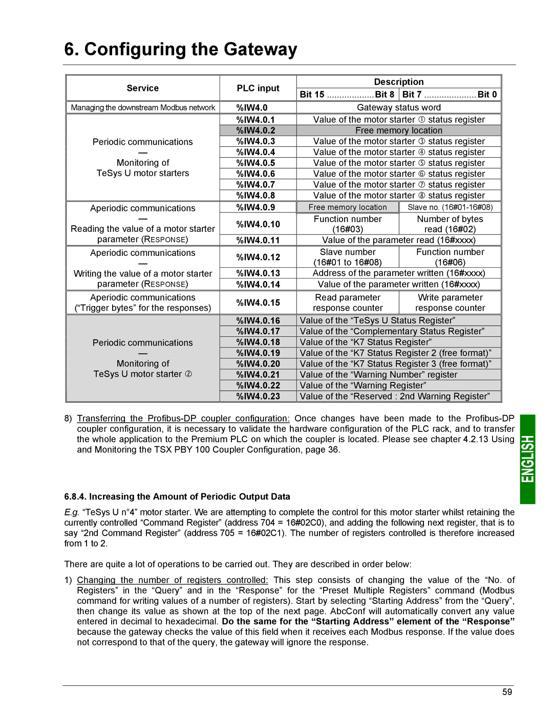
Service | PLC input | Description | ||
Bit 15 ...................Bit 8 |
| Bit 7 ..................... Bit 0 | ||
|
|
| ||
Managing the downstream Modbus network | %IW4.0 | Gateway status word | ||
| %IW4.0.1 | Value of the motor starter c status register | ||
Periodic communications | %IW4.0.20 | Free memory location | ||
%IW4.0.3 | Value of the motor starter e status register | |||
— | %IW4.0.4 | Value of the motor starter f status register | ||
Monitoring of | %IW4.0.5 | Value of the motor starter g status register | ||
TeSys U motor starters | %IW4.0.6 | Value of the motor starter h status register | ||
| %IW4.0.7 | Value of the motor starter i status register | ||
| %IW4.0.8 | Value of the motor starter j status register | ||
Aperiodic communications | %IW4.0.9 | Free memory location |
| Slave no. |
— | %IW4.0.10 | Function number |
| Number of bytes |
Reading the value of a motor starter | (16#03) |
| read (16#02) | |
|
| |||
parameter (RESPONSE) |
|
|
|
|
%IW4.0.11 | Value of the parameter read (16#xxxx) | |||
Aperiodic communications | %IW4.0.12 | Slave number |
| Function number |
— | (16#01 to 16#08) |
| (16#06) | |
|
| |||
Writing the value of a motor starter | %IW4.0.13 | Address of the parameter written (16#xxxx) | ||
parameter (RESPONSE) | %IW4.0.14 | Value of the parameter written (16#xxxx) | ||
Aperiodic communications | %IW4.0.15 | Read parameter |
| Write parameter |
(“Trigger bytes” for the responses) | response counter |
| response counter | |
|
| |||
| %IW4.0.16 | Value of the “TeSys U Status Register” | ||
Periodic communications | %IW4.0.17 | Value of the “Complementary Status Register” | ||
%IW4.0.18 | Value of the “K7 Status Register” | |||
— | %IW4.0.19 | Value of the “K7 Status Register 2 (free format)” | ||
Monitoring of | %IW4.0.20 | Value of the “K7 Status Register 3 (free format)” | ||
TeSys U motor starter d | %IW4.0.21 | Value of the “Warning Number” register | ||
| %IW4.0.22 | Value of the “Warning Register” | ||
| %IW4.0.23 | Value of the “Reserved : 2nd Warning Register” | ||
8)Transferring the
6.8.4. Increasing the Amount of Periodic Output Data
E.g. “TeSys U n°4” motor starter. We are attempting to complete the control for this motor starter whilst retaining the currently controlled “Command Register” (address 704 = 16#02C0), and adding the following next register, that is to say “2nd Command Register” (address 705 = 16#02C1). The number of registers controlled is therefore increased from 1 to 2.
There are quite a lot of operations to be carried out. They are described in order below:
1)Changing the number of registers controlled: This step consists of changing the value of the “No. of Registers” in the “Query” and in the “Response” for the “Preset Multiple Registers” command (Modbus command for writing values of a number of registers). Start by selecting “Starting Address” from the “Query”, then change its value as shown at the top of the next page. AbcConf will automatically convert any value entered in decimal to hexadecimal. Do the same for the “Starting Address” element of the “Response” because the gateway checks the value of this field when it receives each Modbus response. If the value does not correspond to that of the query, the gateway will ignore the response.
59