6. Configuring the Gateway

Constants in Byte, Word or DWord format allow you to relieve the Profibus-DP master by placing the values of these constants in Modbus query frames (constants in “Query” elements) or by comparing them to the values located in the Modbus responses (constants in “Response” elements). These comparisons are used to accept (identical values) or reject (different values) the Modbus responses in the same way as for standard Modbus commands. The Profibus-DP master does not have access to these constants. They are mainly used to replace fields such as “Slave address,” “Function,” “Starting Address,” etc.

Please see the section on “Actions on request/response” in chapter 2.6.4 Transaction and in chapter 2.6.6 Frame objects in the AbcConf user manual, entitled AnyBus Communicator – User Manual for further information about how to handle “Transaction” type commands. This manual can be found on the CD LU9CD1 :

ABC_User_Manual.pdf”.

The LUFP7 gateway’s default configuration includes two “Transaction” commands. These are aperiodic commands used for reading and writing the value of a Modbus slave parameter (necessarily a TeSys U motor starter with the default configuration). They are configured solely for the “TeSys U n°1” node, as the address of the slave is controlled by the Profibus-DP master via the first byte of the “Data” field, which corresponds to the “Slave Address” field in standard Modbus commands. This allows the Profibus-DP master to send this command to all of the Modbus slaves, slave by slave, through the first byte of the “Data” field. The remaining fields of the frames used by these two commands are also placed in the same “Data” field. So the Profibus-DP master has access to all of the content of the frames in these two commands, excluding the checksum.

6.12. Configuring the General Characteristics of the Gateway

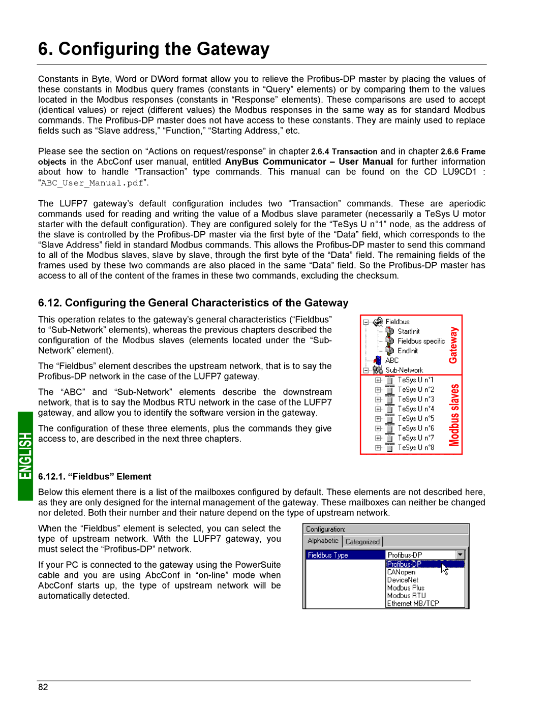
This operation relates to the gateway’s general characteristics (“Fieldbus” to “Sub-Network” elements), whereas the previous chapters described the configuration of the Modbus slaves (elements located under the “Sub- Network” element).

The “Fieldbus” element describes the upstream network, that is to say the Profibus-DP network in the case of the LUFP7 gateway.

The “ABC” and “Sub-Network” elements describe the downstream network, that is to say the Modbus RTU network in the case of the LUFP7 gateway, and allow you to identify the software version in the gateway.

The configuration of these three elements, plus the commands they give access to, are described in the next three chapters.

6.12.1. “Fieldbus” Element

Below this element there is a list of the mailboxes configured by default. These elements are not described here, as they are only designed for the internal management of the gateway. These mailboxes can neither be changed nor deleted. Both their number and their nature depend on the type of upstream network.

When the “Fieldbus” element is selected, you can select the type of upstream network. With the LUFP7 gateway, you must select the “Profibus-DP” network.

If your PC is connected to the gateway using the PowerSuite cable and you are using AbcConf in “on-line” mode when AbcConf starts up, the type of upstream network will be automatically detected.

82

Page 81
Image 81
Schneider Electric LUFP7 user manual Configuring the General Characteristics of the Gateway, Fieldbus Element