7. Appendix A: Technical Characteristics
• | ||||||
gateway specifics | 99); address 0 is not allowed. | |||||
(cont'd) | • | |||||
| • "Resetting to zero" operating mode (input reading and output resetting to zero) | |||||
| not supported. |
|
|
| ||
| • Input synchronisation | |||||
| supported. |
|
|
| ||
| • Gateway address allocated by a master: Service not supported. | |||||
| • Configuration conducted using a specific GSD file. | |||||
| • | |||||
| • Galvanic gateway insulation from the network; D(A) and D(B) signal insulation | |||||
| using |
|
|
| ||
Modbus RTU | • Physical media: RS485 serial link | |||||
characteristics | • Network topology: Multipoint linear topology with adapted line terminations | |||||
| (impedance of 120 Ω in parallel with a capacity of 1 nF) | |||||
| • Communication speed: 1,200 to 57,600 kbits/s | |||||
| • Data bits: 8 |
|
|
| ||
| • Subscriber addresses: | 1 to 247. Address 0 reserved for broadcasting. | ||||
| Addresses 65, 126 and 127 reserved if drivers and/or starters from Schneider | |||||
| Electric are used on the same Modbus network. | |||||
| • Period of silence: Equivalent to the transmission of 3.5 characters. | |||||
Specific Modbus RTU | • Maximum number of subscribers (excluding gateway): 8 Modbus slaves. | |||||
features of the LUFP7 | • Maximum number of commands configured: Up to 50 Modbus queries and | |||||
gateway | responses configured for the same gateway using AbcConf. | |||||
| • Communication speed: 1,200, 2,400, 4,800, 9,600, or 19,200 bits/s, configured | |||||
| using AbcConf. |
|
|
| ||
| • Period of silence: Possibility of increasing the gateway’s period of silence, in | |||||
| 10 ms steps, using AbcConf. | |||||
| • Parity: None, even or uneven, configured using AbcConf. | |||||
| • Start bits: 1 bit, configuration using AbcConf. | |||||
| • Stop bits: 1 or 2 bits, configuration using AbcConf. | |||||
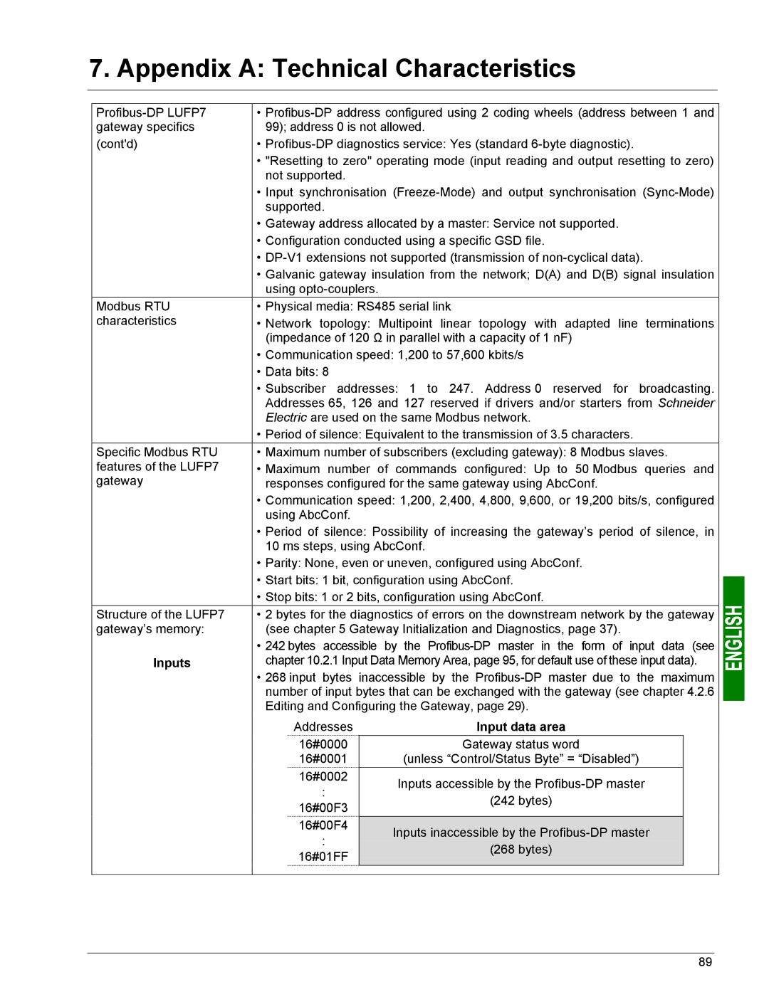
Structure of the LUFP7 | • 2 bytes for the diagnostics of errors on the downstream network by the gateway | |||||
gateway’s memory: | (see chapter 5 Gateway Initialization and Diagnostics, page 37). | |||||
| • 242 bytes accessible by | the | ||||
Inputs | chapter 10.2.1 Input Data Memory Area, page 95, for default use of these input data). | |||||
| • 268 input bytes inaccessible by the | |||||
| number of input bytes that can be exchanged with the gateway (see chapter 4.2.6 | |||||
| Editing and Configuring the Gateway, page 29). | |||||
| Addresses |
| Input data area | |||
| 16#0000 |
|
|
| Gateway status word |
|
| 16#0001 |
|
|
| (unless “Control/Status Byte” = “Disabled”) |
|
| 16#0002 |
|
| Inputs accessible by the |
| |
| : |
|
|
| ||
|
|
|
| (242 bytes) |
| |
| 16#00F3 |
|
|
|
| |
|
|
|
|
| ||
| 16#00F4 |
| Inputs inaccessible by the |
| ||
| : |
|
|
| ||
|
|
|
| (268 bytes) |
| |
| 16#01FF |
|
|
| ||
|
|
|
|
| ||
|
|
|
|
|
|
|
89
