13. Appendix F: Modbus Commands
13.3. “Preset Multiple Registers” Command (16#10)
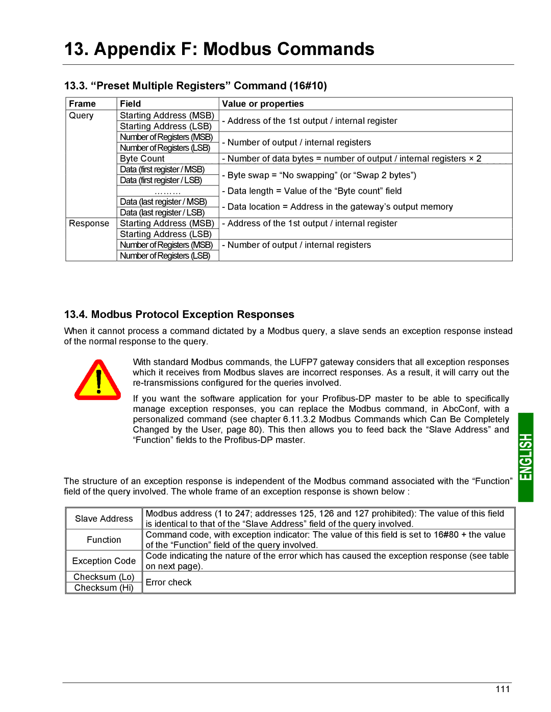
Frame | Field | Value or properties | |
Query | Starting Address (MSB) | - Address of the 1st output / internal register | |
Starting Address (LSB) | |||
|
| ||
| Number of Registers (MSB) | - Number of output / internal registers | |
| Number of Registers (LSB) | ||
|
| ||
| Byte Count | - Number of data bytes = number of output / internal registers × 2 | |
| Data (first register / MSB) | - Byte swap = “No swapping” (or “Swap 2 bytes”) | |
| Data (first register / LSB) | ||
| - Data length = Value of the “Byte count” field | ||
| ……… | ||
| Data (last register / MSB) | - Data location = Address in the gateway’s output memory | |
| Data (last register / LSB) | ||
|
| ||
Response | Starting Address (MSB) | - Address of the 1st output / internal register | |
| Starting Address (LSB) |
| |
| Number of Registers (MSB) | - Number of output / internal registers | |
| Number of Registers (LSB) |
|
13.4. Modbus Protocol Exception Responses
When it cannot process a command dictated by a Modbus query, a slave sends an exception response instead of the normal response to the query.
With standard Modbus commands, the LUFP7 gateway considers that all exception responses which it receives from Modbus slaves are incorrect responses. As a result, it will carry out the
If you want the software application for your
The structure of an exception response is independent of the Modbus command associated with the “Function” field of the query involved. The whole frame of an exception response is shown below :
Slave Address
Function
Exception Code
Checksum (Lo)
Checksum (Hi)
Modbus address (1 to 247; addresses 125, 126 and 127 prohibited): The value of this field is identical to that of the “Slave Address” field of the query involved.
Command code, with exception indicator: The value of this field is set to 16#80 + the value of the “Function” field of the query involved.
Code indicating the nature of the error which has caused the exception response (see table on next page).
Error check
111