10. Appendix C: Default Configuration
10.2. Content of the Gateway’s DPRAM Memory
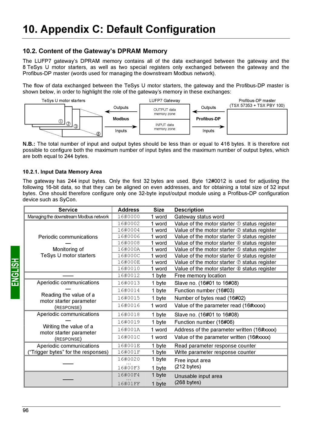
The LUFP7 gateway’s DPRAM memory contains all of the data exchanged between the gateway and the 8 TeSys U motor starters, as well as two special registers only exchanged between the gateway and the
The flow of data exchanged between the TeSys U motor starters, the gateway and the
TeSys U motor starters
c d e
![]()
![]()
![]()
![]()
![]()
![]() j
j![]()
Outputs
Modbus
Inputs
LUFP7 Gateway
OUTPUT data memory zone
INPUT data
memory zone
|
|
|
| |
| Outputs |
| (TSX 57353 + TSX PBY 100) | |
|
|
|
|
|
|
|
| ||
|
|
|
|
|
| Inputs |
|
| |
N.B.: The total number of input and output bytes should be less than or equal to 416 bytes. It is therefore not possible to configure both the maximum number of input bytes and the maximum number of output bytes, which are both equal to 244 bytes.
10.2.1. Input Data Memory Area
The gateway has 244 input bytes. Only the first 32 bytes are used. Byte 12#0012 is used for adjusting the following
Service | Address | Size | Description | |
Managing the downstream Modbus network | 16#0000 | 1 word | Gateway status word | |
| 16#0002 | 1 word | Value of the motor starter c status register | |
Periodic communications | 16#0004 | 1 word | Value of the motor starter d status register | |
16#0006 | 1 word | Value of the motor starter e status register | ||
— | 16#0008 | 1 word | Value of the motor starter f status register | |
Monitoring of | 16#000A | 1 word | Value of the motor starter g status register | |
TeSys U motor starters | 16#000C | 1 word | Value of the motor starter h status register | |
| 16#000E | 1 word | Value of the motor starter i status register | |
| 16#0010 | 1 word | Value of the motor starter j status register | |
16#0012 | 1 byte | Free memory location | ||
Aperiodic communications | 16#0013 | 1 byte | Slave no. (16#01 to 16#08) | |
— | 16#0014 | 1 byte | Function number (16#03) | |
Reading the value of a | 16#0015 | 1 byte | Number of bytes read (16#02) | |
motor starter parameter | ||||
16#0016 | 1 word | Value of the parameter read (16#xxxx) | ||
(RESPONSE) | ||||
Aperiodic communications | 16#0018 | 1 byte | Slave no. (16#01 to 16#08) | |
— | 16#0019 | 1 byte | Function number (16#06) | |
Writing the value of a |
|
|
| |
16#001A | 1 word | Address of the parameter written (16#xxxx) | ||
motor starter parameter | ||||
16#001C | 1 word | Value of the parameter written (16#xxxx) | ||
(RESPONSE) | ||||
Aperiodic communications | 16#001E | 1 byte | Read parameter response counter | |
(“Trigger bytes” for the responses) | 16#001F | 1 byte | Write parameter response counter | |
16#0020 | 1 byte | Free input area | ||
… | … | (212 bytes) | ||
| 16#00F3 | 1 byte | ||
| 16#00F4 | 1 byte | Unusable input area | |
… | … | |||
(268 bytes) | ||||
| 16#01FF | 1 byte |
96