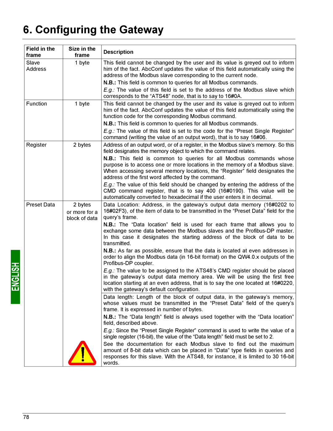
6. Configuring the Gateway
Field in the | Size in the | Description | |
frame | frame | ||
| |||
Slave | 1 byte | This field cannot be changed by the user and its value is greyed out to inform | |
Address |
| him of the fact. AbcConf updates the value of this field automatically using the | |
|
| address of the Modbus slave corresponding to the current node. | |
|
| N.B.: This field is common to queries for all Modbus commands. | |
|
| E.g.: The value of this field is set to the address of the Modbus slave which | |
|
| corresponds to the “ATS48” node, that is to say to 16#0A. | |
Function | 1 byte | This field cannot be changed by the user and its value is greyed out to inform | |
|
| him of the fact. AbcConf updates the value of this field automatically using the | |
|
| function code for the corresponding Modbus command. | |
|
| N.B.: This field is common to queries for all Modbus commands. | |
|
| E.g.: The value of this field is set to the code for the “Preset Single Register” | |
|
| command (writing the value of an output word), that is to say 16#06. | |
Register | 2 bytes | Address of an output word, or of a register, in the Modbus slave’s memory. So this | |
|
| field designates the memory object to which the command relates. | |
|
| N.B.: This field is common to queries for all Modbus commands whose | |
|
| purpose is to access one or more locations in the memory of a Modbus slave. | |
|
| When accessing several memory locations, the “Register” field designates the | |
|
| address of the first word affected by the command. | |
|
| E.g.: The value of this field should be changed by entering the address of the | |
|
| CMD command register, that is to say 400 (16#0190). This value will be | |
|
| automatically converted to hexadecimal if the user enters it in decimal. | |
Preset Data | 2 bytes | Data Location: Address, in the gateway’s output data memory (16#0202 to | |
| or more for a | 16#02F3), of the item of data to be transmitted in the “Preset Data” field for the | |
| block of data | query’s frame. | |
|
| N.B.: The “Data location” field is used for each frame that allows you to | |
|
| exchange some data between the Modbus slaves and the | |
|
| In this case it designates the starting address of the block of data to be | |
|
| transmitted. | |
|
| N.B.: As far as possible, ensure that the data is located at even addresses in | |
|
| order to align the Modbus data (in | |
|
| ||
|
| E.g.: The value to be assigned to the ATS48’s CMD register should be placed | |
|
| in the gateway’s output data memory area. We will be using the first free | |
|
| location starting at an even address, that is to say the one located at 16#0220, | |
|
| with the gateway’s default configuration. | |
|
| Data length: Length of the block of output data, in the gateway’s memory, | |
|
| whose values must be transmitted in the “Preset Data” field of the query’s | |
|
| frame. It is expressed in number of bytes. | |
|
| N.B.: The “Data length” field is always used together with the “Data location” | |
|
| field, described above. | |
|
| E.g.: Since the “Preset Single Register” command is used to write the value of a | |
|
| single register | |
|
| See the documentation for each Modbus slave to find out the maximum | |
|
| amount of | |
|
| responses for this slave. With the ATS48, for instance, it is limited to 30 | |
|
| words. |
78
